
Concept explainers
Videos
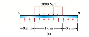
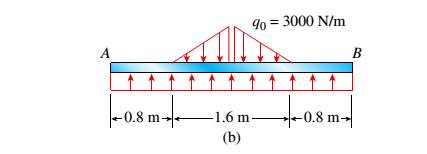
The beam AB shown in the figure supports a uniform load of intensity 3000 N/m acting over half the length of the beam. The beam rests on a foundation that produces a uniformly distributed load over the entire length.
- Draw the shear-force and bending-moment diagrams for this beam.
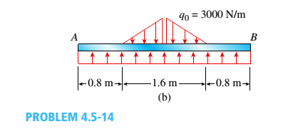
Repeat part (a) for the distributed load variation shown in Fig. b.
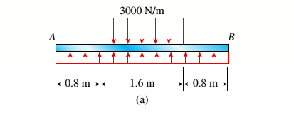
(a)
The shear force and bending moment diagram for the given beam.
Answer to Problem 4.5.14P
Maximum shear force Vmax= y13
Maximum bending moment Mmax=
Explanation of Solution
Given information: The given beam and parameters are shown in the figure below:
For calculating the maximum shear force (V) and bending moment (M) of the given figure, we need to find the amount of force acting upwards on the entire span length.
Shear Force Diagram:
To find the shear force of the given figure, we divide the above figure in a number of sections.
- Firstly taking a section from length 0 to 0.8 m.
- Again taking a section from length 0.8 m to mid-span.
- For the next half of the beam, the shear values can be obtained from the concept of symmetry and the obtained values is shown below in the given shear force diagram.
The value of shear force when x= 0 at point A is
The value of shear force when x= 0.8 at point A is
The value of shear force when x= 0.8 is,
The value of shear force at mid- span when x= 1.6 is,
Bending Moment Diagram:
To find the bending moments of the given figure, we divide the above figure in a number of sections.
- Firstly taking a section from length 0 to 0.8 m.
- Again taking a section from length 0.8 m to mid-span.
- For the next half of the beam, the bending moment values can be obtained from the concept of symmetry and the obtained values is shown below in the given bending moment diagram.
As the equation is of second order of degree, the curve obtained is a parabola.
The value of Moment when x= 0 at point A is
The value of moment when x= 0.8 at point A is
The value of bending moment when x= 0.8 is,
The value of bending moment at mid- span when x= 1.6 is,
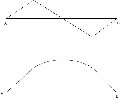
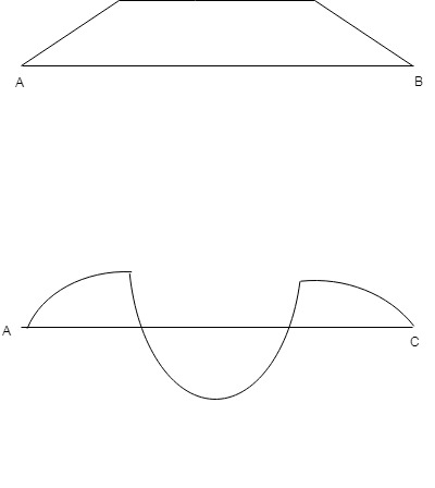
On the basis of above calculation the shear force and bending moment diagram for the given beam is as follows:
(b)
The shear force and bending moment diagram for the given beam.
Answer to Problem 4.5.14P
Maximum shear force Vmax=
Maximum bending moment Mmax=
Explanation of Solution
Given information: The given beam and parameters are shown in the figure below:
For calculating the maximum shear force (V) and bending moment (M) of the given figure, we need to find the amount of force acting upwards on the entire span length.
Shear Force Diagram:
To find the shear force of the given figure we divide the above figure in a number of sections.
- Firstly taking a section from length 0 to 0.8 m.
- Again taking a section from length 0.8 m to mid-span. For obtaining the required shear force value, consider a section X-X for the given uniformly varying load.
- For the next half of the beam, the shear values can be obtained from the concept of symmetry and the obtained values is shown below in the given shear force diagram.
The value of shear force when x= 0 at point A is
The value of shear force when x= 0.8 at point A is
From the triangle similarity,
The value of shear force when x= 0.8 is,
The value of shear force at mid- span when x= 2.4 is,
Bending Moment Diagram:
To find the bending moments of the given figure we divide the above figure in a number of sections.
- Firstly taking a section from length 0 to 0.8 m.
- For obtaining the required shear force value, consider a section X-X for the given uniformly varying load. From the triangle similarity,
- For the next half of the beam, the bending moment values can be obtained from the concept of symmetry and the obtained values is shown below in the given bending moment diagram.
As the equation is of second order of degree, the curve obtained is a parabola.
The value of Moment when x= 0 at point A is
The value of moment when x= 0.8 at point A is
The value of bending moment when x= 0.8 is,
The value of bending moment at mid- span when x= 1.6 is,
On the basis of above calculation the shear force and bending moment diagram for the given beam is as follows:
Want to see more full solutions like this?
Chapter 4 Solutions
Mechanics of Materials (MindTap Course List)


- At a full d raw, an archer applies a pull of 130 N to the bowstring of the bow shown in the figure. Determine the bending moment at the midpoint of the bow.arrow_forwardA steel beam of length L = 16 in. and cross-sectional dimensions h = 0.6 in. and h = 2 in. (see figure) supports a uniform load of intensity if = 240 lb/in., which includes the weight of the beam. Calculate the shear stresses in the beam (at the cross section of maximum shear force) at points located 1/4 in., 1/2 in., 3/4 in., and I in, from the top surface of the beam. From these calculations, plot a graph showing the distribution of shear stresses from top to bottom of the beam.arrow_forwardDraw the shear-Force and bending-moment diagrams for a simple beam AB supporting two equal concentrated loads P (see figure). Repeat if the left-hand load is upward and the right-hand load is downward.arrow_forward
- Beam ABCD represents a reinforced-concrete foundation beam that supports a uniform load of intensity q1= 3500 lb/ft (see figure). Assume that the soil pressure on the underside of the beam is uniformly distributed with intensity q2 Find the shear force VBand bending moment MBat point B. Find the shear force Vmand bending moment M at the midpoint of the beam.arrow_forwardA wood beam AB on simple supports with span length equal to 10 ft is subjected to a uniform load of intensity 125 lb/ft acting along the entire length of the beam, a concentrated load of magnitude 7500 lb acting at a point 3 ft from the right-hand support, and a moment at A of 18,500 ft-lb (sec figure). The allowable stresses in bending and shear, respectively, are 2250 psi and 160 psi. From the table in Appendix G, select the lightest beam that will support the loads (disregard the weight of the beam). Taking into account the weight of the beam (weight density = 35 lb/ft3), verify that the selected beam is satisfactory, or if it is not, select a new beam.arrow_forwardCantilever beam AB carries an upward uniform load of intensity q1from x = 0 to L/2 (see Fig. a) and a downward uniform load of intensity q from x = L/2 to L. Find q1in terms of q if the resulting moment at A is zero. Draw V and M diagrams for the case of both q and qtas applied loadings. Repeat part (a) for the case of an upward triangularly distributed load with peak intensity q0(see Fig. b). For part (b), find q0, instead of q1arrow_forward
- The beam ABC shown in the figure is simply supported at A and B and has an overhang from B to C Draw the shear-force and bending-moment diagrams for beam ABC. Note: Disregard the widths of the beam and vertical arm and use centerline dimensions when making calculations.arrow_forwardA simply supported wood beam having a span length L = 12 ft is subjected to unsymmetrical point loads, as shown in the figure. Select a suitable size for the beam from the table in Appendix G. The allowable bending stress is 1800 psi and the wood weighs 35 Lb/ft3.arrow_forwardA beam ABCD with a vertical arm CE is supported as a simple beam at .1 and D (see figure). A cable passes over a small pulley that is attached to the arm at E. One end of the cable is attached to the beam at point B. The tensile force in the cable is 1800 lb. Draw the shear-Force and bending-moment diagrams for beam A BCD. Note: Disregard the widths of the beam and vertical arm and use centerline dimensions when making calculations. Repeat part (a) if a roller support is added at C and a shear release is inserted just left of C (see figure part b).arrow_forward
- Find expressions for shear force V and moment Mat x = 2L/3 of beam (a) in terms of peak load intensity q0 and beam length variable L. Repeat for beam (b).arrow_forwardDraw the shear-force and bending-moment diagrams for a cantilever beam AB acted upon by two different load cases. A distributed load with linear variation and maximum intensity q0(see figure part a). A distributed load with parabolic variation and maximum intensity q0(see figure part b).arrow_forwardThe beam ABC shown in the figure is simply supported at A and B and has an overhang from B to C. The loads consist of a horizontal force P1= 4,0 kN acting at the end of a vertical arm and a vertical force P2= 8.0 kN acting at the end of the overhang, Determine the shear force Fand bending moment M at a cross section located 3,0 m from the left-hand support. Note: Disregard the widths of the beam and vertical arm and use centerline dimensions when making calculations, Find the value of load A that results in V = 0 at a cross section located 2.0 m from the left-hand support. If P2= 8.0 kN, find the value of load P1that results in M = 0 at a cross section located 2,0 m from the left-hand support.arrow_forward
 Mechanics of Materials (MindTap Course List)Mechanical EngineeringISBN:9781337093347Author:Barry J. Goodno, James M. GerePublisher:Cengage Learning