
Mechanics of Materials
11th Edition
ISBN: 9780137605460
Author: Russell C. Hibbeler
Publisher: Pearson Education (US)
expand_more
expand_more
format_list_bulleted
Concept explainers
Videos
Textbook Question
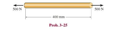
Chapter 3.7, Problem 25P
The acrylic plastic rod is
Expert Solution & Answer
Want to see the full answer?
Check out a sample textbook solution
Students have asked these similar questions
The acrylic plastic rod is 200 mm long and 15 mm in diameter. If an axial load of 300 N is applied to it, determine the change in its length and the change in its diameter. Ep = 2.70 GPa, np = 0.4.
A uniform edge load of 500 lb>in. and 350 lb>in. is applied to the polystyrene specimen. If the specimen is originally square and has dimensions of a = 2 in., b = 2 in., and a thickness of t = 0.25 in., determine its new dimensions a , b , and t after the load is applied. Ep = 597(103) psi andnp = 0.25.
In the graft, the 6-meter-high arm is manufactured using the l profile given below. It is fixed to both ends of the arm with a built-in support. If the yield strength of the material is σy=400 MPa Elasticity modulus E=2*105 MPa If the safety factor used in the design is 2.5, the arm in question is What is the highest axial load it can safely carry?
Chapter 3 Solutions
Mechanics of Materials
Ch. 3.4 - Define a homogeneous material.Ch. 3.4 - Indicate the points on the stress-strain diagram...Ch. 3.4 - Define the modulus of elasticity E.Ch. 3.4 - At room temperature, mild steel is a ductile...Ch. 3.4 - Engineering stress and strain are calculated using...Ch. 3.4 - As the temperature increases the modulus of...Ch. 3.4 - A 100-mm-long rod has a diameter of 15 mm. If an...Ch. 3.4 - A bar has a length of 8 in. and cross-sectional...Ch. 3.4 - A 10-mm-diameter rod has a modulus of elasticity...Ch. 3.4 - The material for the 50-mm-long specimen has the...
Ch. 3.4 - The material for the 50-mm-long specimen has the...Ch. 3.4 - If the elongation of wire BC is 0.2 mm after the...Ch. 3.4 - Data taken from a stress-strain test for a ceramic...Ch. 3.4 - The stress-strain diagram for a steel alloy having...Ch. 3.4 - The stress-strain diagram for a steel alloy having...Ch. 3.4 - The stress-strain diagram for a steel alloy having...Ch. 3.4 - Determine the elongation of the square hollow bar...Ch. 3.4 - The stress-strain diagram for an aluminum alloy...Ch. 3.4 - The stress-strain diagram for an aluminum alloy...Ch. 3.4 - The stress-strain diagram for an aluminum alloy...Ch. 3.4 - A structural member in a nuclear reactor is made...Ch. 3.4 - The rigid pipe is supported by a pin at A and an...Ch. 3.4 - The rigid pipe is supported by a pin at A and an...Ch. 3.4 - Direct tension indicators are sometimes used...Ch. 3.4 - A tension test was performed on a magnesium alloy...Ch. 3.4 - The stress-strain diagram for a bone is shown and...Ch. 3.4 - The two bars are made of a material that has the...Ch. 3.4 - The two bars are made of a material that has the...Ch. 3.7 - A 100-mm-long rod has a diameter of 15 mm. If an...Ch. 3.7 - A solid circular rod that is 600 mm long and 20 mm...Ch. 3.7 - A 20-mm-wide block is firmly bonded to rigid...Ch. 3.7 - A 20-mm-wide block is bonded to rigid plates at...Ch. 3.7 - The acrylic plastic rod is 400mm long and 20mm in...Ch. 3.7 - The elastic portion of the stress-strain diagram...Ch. 3.7 - The elastic portion of the stress-strain diagram...Ch. 3.7 - The lap joint is connected together using a 1.25...Ch. 3.7 - The lap joint is connected together using a 1.25...Ch. 3.7 - Prob. 32PCh. 3.7 - The thin-walled tube is subjected to an axial...Ch. 3 - The elastic portion of the tension stress-strain...Ch. 3 - The elastic portion of the tension stress-strain...Ch. 3 - The rigid beam rests in the horizontal position on...Ch. 3 - The wires each have a diameter of 12 in., length...Ch. 3 - Prob. 5RPCh. 3 - diameter steel bolts. If the clamping force in...Ch. 3 - The stress-strain diagram for polyethylene, which...Ch. 3 - The pipe with two rigid caps attached to its ends...Ch. 3 - The 8-mm-diameter bolt is made of an aluminum...Ch. 3 - An acetal polymer block is fixed to the rigid...
Knowledge Booster


Learn more about
Need a deep-dive on the concept behind this application? Look no further. Learn more about this topic, mechanical-engineering and related others by exploring similar questions and additional content below.Similar questions
- The pin-connected assembly consists of aluminum rods (1) and (2) and steel rod (3). The aluminum rods each have a diameter of 14 mm and an elastic modulus of E = 70 GPa. The steel rod has a diameter of 15 mm and an elastic modulus of E= 180 GPa. Assume a = 3.0 m, b = 1.6 m, and c = 1.0 m. What is the magnitude of load P that is necessary to displace point A 7mm to the left? A Answer: P = i (3) eTextbook and Media Save for Later B b D kN Attempts: 0 of 5 used Submit Answerarrow_forwardThe pin-connected assembly consists of aluminum rods (1) and (2) and steel rod (3). The aluminum rods each have a diameter of 14 mm and an elastic modulus of E = 70 GPa. The steel rod has a diameter of 15 mm and an elastic modulus of E= 180 GPa. Assume a = 3.0 m, b = 1.6 m, and c = 1.0 m. What is the magnitude of load P that is necessary to displace point A 7 mm to the left? A Answer: P = i (3) eTextbook and Media Save for Later B b D kN Attempts: 0 of 5 used Submit Answerarrow_forwardThe acrylic plastic rod is 200 mm long and 15 mm in diameter. If an axial load of 300 N is applied to it, what is the change in its diameter? E, = 2.70 GPa, v, = 0.5. 300 N 300 N 200 mm Select one: a. -4.72 µm O b. -6.29 µm C. -3.77 µm d. 3.77 µm е. 4.72 um O f. Nonearrow_forward
- The pin-connected assembly consists of aluminum rods (1) and (2) and steel rod (3). The aluminum rods each have a diameter of 18 mm and an elastic modulus of E = 71 GPa. The steel rod has a diameter of 16 mm and an elastic modulus of E = 200 GPa. Assume a = 3.5 m, b = 1.4 m, and c = 1.1 m. What is the magnitude of load P that is necessary to displace point A 13 mm to the left? B Answer: P = i KNarrow_forwardA 100-mm-long rod has a diameter of 15 mm. If an axial tensile load of 100 kN is applied, determine its change in length. Assume linear elastic behavior with E = 200 GPa.arrow_forwardThe pin-connected assembly consists of aluminum rods (1) and (2) and steel rod (3). The aluminum rods each have a diameter of 14 mm and an elastic modulus of E= 65 GPa. The steel rod has a diameter of 18 mm and an elastic modulus of E= 215 GPa. Assume a = 3.2 m, b = 1.3 m, and c = 1.4 m. What is the magnitude of load P that is necessary to displace point A 10 mm to the left? (1) (3) A 4 Answer: P = i B (2) D KNarrow_forward
- A 100-mm-long rod has a diameter of 15 mm. If an axial tensile load of 10 kN is applied to it, determine the change in its diameter. E = 70 GPa, n = 0.35.arrow_forwardA 100-mm long rod has a diameter of 15 mm. If an axial tensile load of 165 kN is applied, determine its change in length. Assume linear-elastic behavior with E = 200 GPa.arrow_forwardA steel bar 300 mm long, 50 mm wide and 40 mm thick is subjected to a pull of 300 kN in the direction of length. Determine the change in volume. Take E = 2x10⁵ N/mm2and μ= 0.25.arrow_forward
- A plastic rod is 200mm long and 15mm in diameter. If a tensile load of 300N is applied to it, determine the change in its length and the change in its diameter. Assume Modulus of elasticity (E) = 2.70 GPa, and poisson's ratio (v) = 0.4. indicate free body diagramarrow_forwardA uniform edge load of 400 lb/in. and 300 lb/in. is applied to the thin plane specimen shown below. If the specimen is originally square and has dimensions of a = 2 in., b = 2 in., and a thickness of t = 0.25 in., determine its new dimensions a', b', and t' after the load is applied. Elastic modulus E = 600 x 103 psi and Poisson's ratio v = 0.3. 300 lb/in. a = 2 in. 400 lb/in. 300 lb/in. b = 2 in. 400 lb/in.arrow_forwardThe pole is supported by a pin at B and A-36 steel guy wire AC. If the wire has a diameter of 0.2. Modulus of Elasticity of Steel = 200GPA or 29x103 ksi Poisson's ratio of steel=0.321 a. Determine how much the wire stretches when the horizontal force acts on the pole. 3 ft 30 D 2.5 kip 4 ft B b. Determine the change in the wire's radius c. At what angle is the principal stresses on pole BC? Use Mohr's Circle. d. What is the principal stress in pol BC? Use Mohr's Circle e. Draw the stresses on a unit element acting on 35-degree clockwise direction of pole BC. Use Mohr's Circle. f. What are the principal stresses in point D? Use Mohr's Circle. (answer in ksi) g. At what angle is the principal stresses acting on point D? Use Mohr 's Circle. h. Draw the stresses on a unit element acting on 35degree-clockwise direction of point D. Use Mohr's Circle. (answer in ksi)arrow_forward
arrow_back_ios
SEE MORE QUESTIONS
arrow_forward_ios
Recommended textbooks for you
 Elements Of ElectromagneticsMechanical EngineeringISBN:9780190698614Author:Sadiku, Matthew N. O.Publisher:Oxford University Press
 Mechanics of Materials (10th Edition)Mechanical EngineeringISBN:9780134319650Author:Russell C. HibbelerPublisher:PEARSON
 Thermodynamics: An Engineering ApproachMechanical EngineeringISBN:9781259822674Author:Yunus A. Cengel Dr., Michael A. BolesPublisher:McGraw-Hill Education
 Control Systems EngineeringMechanical EngineeringISBN:9781118170519Author:Norman S. NisePublisher:WILEY
 Mechanics of Materials (MindTap Course List)Mechanical EngineeringISBN:9781337093347Author:Barry J. Goodno, James M. GerePublisher:Cengage Learning
 Engineering Mechanics: StaticsMechanical EngineeringISBN:9781118807330Author:James L. Meriam, L. G. Kraige, J. N. BoltonPublisher:WILEY
Elements Of Electromagnetics
Mechanical Engineering
ISBN:9780190698614
Author:Sadiku, Matthew N. O.
Publisher:Oxford University Press
Mechanics of Materials (10th Edition)
Mechanical Engineering
ISBN:9780134319650
Author:Russell C. Hibbeler
Publisher:PEARSON
Thermodynamics: An Engineering Approach
Mechanical Engineering
ISBN:9781259822674
Author:Yunus A. Cengel Dr., Michael A. Boles
Publisher:McGraw-Hill Education
Control Systems Engineering
Mechanical Engineering
ISBN:9781118170519
Author:Norman S. Nise
Publisher:WILEY
Mechanics of Materials (MindTap Course List)
Mechanical Engineering
ISBN:9781337093347
Author:Barry J. Goodno, James M. Gere
Publisher:Cengage Learning
Engineering Mechanics: Statics
Mechanical Engineering
ISBN:9781118807330
Author:James L. Meriam, L. G. Kraige, J. N. Bolton
Publisher:WILEY
EVERYTHING on Axial Loading Normal Stress in 10 MINUTES - Mechanics of Materials; Author: Less Boring Lectures;https://www.youtube.com/watch?v=jQ-fNqZWrNg;License: Standard YouTube License, CC-BY