
Mechanics of Materials
11th Edition
ISBN: 9780137605460
Author: Russell C. Hibbeler
Publisher: Pearson Education (US)
expand_more
expand_more
format_list_bulleted
Concept explainers
Videos
Textbook Question
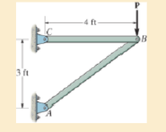
Chapter 3.4, Problem 22P
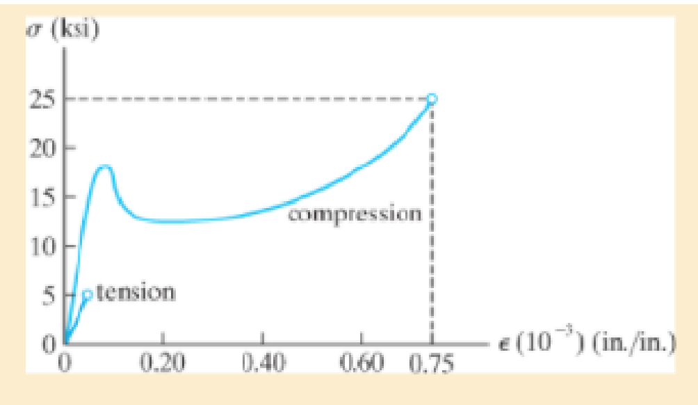
The two bars are made of a material that has the stress-strain diagram shown. Determine the cross-sectional area of each bar so that the bars fracture simultaneously when the load P = 3 kip. Assume that buckling does not occur.
Expert Solution & Answer
Want to see the full answer?
Check out a sample textbook solution
Students have asked these similar questions
The elastic portion of the stress-
strain diagram for the 2014-T6
aluminum is shown in the figure.
A short cylindrical block, made of
this material and has a diameter
of 22 mm, is placed in the smooth
jaws of a vise, and squeezed until
the axial load applied is P= 45
kN. If the material has a Poisson's
ratio of = 0.35, determine the
new diameter (mm) of the
cylindrical block.
Nylon strips are fused to glass plates. When moderately heated the nylon
will become soft while the glass stays approximately rigid. Determine the
average shear strain in the nylon due to the load P when the assembly
deforms as indicated.
2 mm
P.
3 mm
5 mm
3 mm
5 mm
3 mm
The elastic portion of the stress–strain diagram for an aluminum alloy is shown in the figure. The specimen from which it was obtained has an original diameter of 12.7 mm and a gage length of 50.8 mm. If a load of P = 60 kN is applied to the specimen, determine its new diameter and length. Taken = 0.35.
Chapter 3 Solutions
Mechanics of Materials
Ch. 3.4 - Define a homogeneous material.Ch. 3.4 - Indicate the points on the stress-strain diagram...Ch. 3.4 - Define the modulus of elasticity E.Ch. 3.4 - At room temperature, mild steel is a ductile...Ch. 3.4 - Engineering stress and strain are calculated using...Ch. 3.4 - As the temperature increases the modulus of...Ch. 3.4 - A 100-mm-long rod has a diameter of 15 mm. If an...Ch. 3.4 - A bar has a length of 8 in. and cross-sectional...Ch. 3.4 - A 10-mm-diameter rod has a modulus of elasticity...Ch. 3.4 - The material for the 50-mm-long specimen has the...
Ch. 3.4 - The material for the 50-mm-long specimen has the...Ch. 3.4 - If the elongation of wire BC is 0.2 mm after the...Ch. 3.4 - Data taken from a stress-strain test for a ceramic...Ch. 3.4 - The stress-strain diagram for a steel alloy having...Ch. 3.4 - The stress-strain diagram for a steel alloy having...Ch. 3.4 - The stress-strain diagram for a steel alloy having...Ch. 3.4 - Determine the elongation of the square hollow bar...Ch. 3.4 - The stress-strain diagram for an aluminum alloy...Ch. 3.4 - The stress-strain diagram for an aluminum alloy...Ch. 3.4 - The stress-strain diagram for an aluminum alloy...Ch. 3.4 - A structural member in a nuclear reactor is made...Ch. 3.4 - The rigid pipe is supported by a pin at A and an...Ch. 3.4 - The rigid pipe is supported by a pin at A and an...Ch. 3.4 - Direct tension indicators are sometimes used...Ch. 3.4 - A tension test was performed on a magnesium alloy...Ch. 3.4 - The stress-strain diagram for a bone is shown and...Ch. 3.4 - The two bars are made of a material that has the...Ch. 3.4 - The two bars are made of a material that has the...Ch. 3.7 - A 100-mm-long rod has a diameter of 15 mm. If an...Ch. 3.7 - A solid circular rod that is 600 mm long and 20 mm...Ch. 3.7 - A 20-mm-wide block is firmly bonded to rigid...Ch. 3.7 - A 20-mm-wide block is bonded to rigid plates at...Ch. 3.7 - The acrylic plastic rod is 400mm long and 20mm in...Ch. 3.7 - The elastic portion of the stress-strain diagram...Ch. 3.7 - The elastic portion of the stress-strain diagram...Ch. 3.7 - The lap joint is connected together using a 1.25...Ch. 3.7 - The lap joint is connected together using a 1.25...Ch. 3.7 - Prob. 32PCh. 3.7 - The thin-walled tube is subjected to an axial...Ch. 3 - The elastic portion of the tension stress-strain...Ch. 3 - The elastic portion of the tension stress-strain...Ch. 3 - The rigid beam rests in the horizontal position on...Ch. 3 - The wires each have a diameter of 12 in., length...Ch. 3 - Prob. 5RPCh. 3 - diameter steel bolts. If the clamping force in...Ch. 3 - The stress-strain diagram for polyethylene, which...Ch. 3 - The pipe with two rigid caps attached to its ends...Ch. 3 - The 8-mm-diameter bolt is made of an aluminum...Ch. 3 - An acetal polymer block is fixed to the rigid...
Knowledge Booster


Learn more about
Need a deep-dive on the concept behind this application? Look no further. Learn more about this topic, mechanical-engineering and related others by exploring similar questions and additional content below.Similar questions
- 8-21. The elastic portion of the stress-strain diagram for an aluminum alloy is shown in the figure. The specimen from which it was obtained has an original diameter of 12.7 mm and a gage length of 50.8 mm. When the applied load on the specimen is 50 kN, the diameter is 12.67494 mm. Determine Poisson's ratio for the material. 8-22. The elastic portion of the stress-strain diagram for an aluminum alloy is shown in the figure. The specimen from which it was obtained has an original diameter of 12.7 mm and a gage length of 50.8 mm. If a load of P = 60 kN is applied to the specimen, determine its new diameter and length. Take v = 0.35. σ (MPa) 490 0.007 Probs. 8-21/22 € (mm/mm)arrow_forwardThe shear stress–strain diagram for an alloy is shown in the figure. If a bolt having a diameter of 0.25 in. is made of this material and used in the lap joint, determine the modulus of elasticity E and the force P required to cause the material to yield. Take n = 0.3.arrow_forwardA bar has a length of 200 mm and cross-sectional area of 7500 mm2. Determine the modulus ofelasticity of the material if it is subjected to an axial tensile load of 50 kN and stretches 0.075 mm.The material has linear-elastic behavior.arrow_forward
- 4. Nylon strips are fused to glass plates. When moderately heated the nylon will become soft while the glass stays approximately rigid. Determine the average shear strain in the nylon due to the load P when the assembly deforms as indicated. y 2 mm 3 mm P 5 mm 3 mm 5 mm 3 mmarrow_forwardA stepped circular bar having diameters of 20 mm, 15 mm, and 10 mm over axial lengths of 100 mm, 80 mm and 60 mm is subjected to an axial tensile force of 5 kN If E= 100 GPa and ν= 0.32 for the material of the bar determine: Total change in length. Change in each diameter.arrow_forwardThe rod is 200 mm long and 60 mm in diameter. If an axial load of 300 N is applied to it, determine the change in its length, the change in its diameter, normal stress and normal strain. The Poisson's ratio is 0.4 and the modulus of elasticity is 20 GPa.arrow_forward
- A 100-mm long rod has a diameter of 15 mm. If an axial tensile load of 165 kN is applied, determine its change in length. Assume linear-elastic behavior with E = 200 GPa.arrow_forwardThe stress-strain diagram for a material is shown in the figure below for its elastic portion.A specimen from this material has a diameter of 16mm and a length of 60mm. A tensile loadof 30kN is applied to the specimen. Determine its diameter and length following the applicationof this load. Poisson’s ratio for the material is 0.4.arrow_forwardThe pin-connected assembly consists of aluminum rods (1) and (2) and steel rod (3). The aluminum rods each have a diameter of 19 mm and an elastic modulus of E = 68 %3D GPa. The steel rod has a diameter of 15 mm and an elastic modulus of E = 215 GPa. %3D Assume a = 3.0 m, b = 1.9 m, and c = 0.8 m. What is the magnitude of load P that is necessary to displace point A 14 mm to the left? a b (1) (3) A B (2) Darrow_forward
- A solid circular rod that is 600 mm long and 20 mm in diameter is subjected to an axial force of P = 50 kN. The elongation of the rod is d = 1.40 mm, and its diameter becomes d = 19.9837 mm. Determine the modulus of elasticity and the modulus of rigidity of the material. Assume that the material does not yield.arrow_forwardThe stress-strain diagram for an aluminum alloy specimen having an original diameter of 0.5 in. and a gauge length of 2 in. is given in the figure. If the specimen is loaded until it is stressed to 60 ksi, determine the approximate amount of elastic recovery and the increase in the gage length after it is unloaded.arrow_forwardThe stepped rod is made up of two different materials A and B of lengths 80 cm and 1.2 m respectively. The diameters of materials B and A are 2.5 and 3.5 cm respectively. The modulus of elasticity of materials A and B are 250 and 150 GPa respectively. The elongation of the rod is the same for both the materials. A total tensile load of 40 kN is applied to both the materials A and B together. Calculate the load in each material.arrow_forward
arrow_back_ios
SEE MORE QUESTIONS
arrow_forward_ios
Recommended textbooks for you
 Elements Of ElectromagneticsMechanical EngineeringISBN:9780190698614Author:Sadiku, Matthew N. O.Publisher:Oxford University Press
 Mechanics of Materials (10th Edition)Mechanical EngineeringISBN:9780134319650Author:Russell C. HibbelerPublisher:PEARSON
 Thermodynamics: An Engineering ApproachMechanical EngineeringISBN:9781259822674Author:Yunus A. Cengel Dr., Michael A. BolesPublisher:McGraw-Hill Education
 Control Systems EngineeringMechanical EngineeringISBN:9781118170519Author:Norman S. NisePublisher:WILEY
 Mechanics of Materials (MindTap Course List)Mechanical EngineeringISBN:9781337093347Author:Barry J. Goodno, James M. GerePublisher:Cengage Learning
 Engineering Mechanics: StaticsMechanical EngineeringISBN:9781118807330Author:James L. Meriam, L. G. Kraige, J. N. BoltonPublisher:WILEY
Elements Of Electromagnetics
Mechanical Engineering
ISBN:9780190698614
Author:Sadiku, Matthew N. O.
Publisher:Oxford University Press
Mechanics of Materials (10th Edition)
Mechanical Engineering
ISBN:9780134319650
Author:Russell C. Hibbeler
Publisher:PEARSON
Thermodynamics: An Engineering Approach
Mechanical Engineering
ISBN:9781259822674
Author:Yunus A. Cengel Dr., Michael A. Boles
Publisher:McGraw-Hill Education
Control Systems Engineering
Mechanical Engineering
ISBN:9781118170519
Author:Norman S. Nise
Publisher:WILEY
Mechanics of Materials (MindTap Course List)
Mechanical Engineering
ISBN:9781337093347
Author:Barry J. Goodno, James M. Gere
Publisher:Cengage Learning
Engineering Mechanics: Statics
Mechanical Engineering
ISBN:9781118807330
Author:James L. Meriam, L. G. Kraige, J. N. Bolton
Publisher:WILEY
Stresses Due to Fluctuating Loads Introduction - Design Against Fluctuating Loads - Machine Design 1; Author: Ekeeda;https://www.youtube.com/watch?v=3FBmQXfP_eE;License: Standard Youtube License