
Mechanics of Materials
11th Edition
ISBN: 9780137605460
Author: Russell C. Hibbeler
Publisher: Pearson Education (US)
expand_more
expand_more
format_list_bulleted
Concept explainers
Videos
Textbook Question
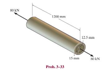
Chapter 3.7, Problem 33P
The thin-walled tube is subjected to an axial force of
Expert Solution & Answer
Want to see the full answer?
Check out a sample textbook solution
Students have asked these similar questions
The pipe with two rigid caps attached to its ends is subjected to an axial force P. If the pipe is made from a material having a modulus of elasticity E and Poisson’s ratio n, determine the change in volume of the material.
The 2-m-long tube is made of an elastic perfectly plastic material as shown. Determine the applied torque T, which subjects the material at the tube’s outer edge to a shear strain of gmax = 0.006 rad. What would be the permanent angle of twist of the tube when this torque is removed? Sketch the residual stress distribution in the tube
The friction pad A is used to support the member,which is subjected to an axial force of P = 2 kN. Thepad is made from a material having a modulus ofelasticity of E = 4 MPa and Poisson’s ratio n = 0.4.If slipping does not occur, determine the normaland shear strains in the pad. The width is 50 mm.Assume that the material is linearly elastic. Also,neglect the effect of the moment acting on the pad.
Chapter 3 Solutions
Mechanics of Materials
Ch. 3.4 - Define a homogeneous material.Ch. 3.4 - Indicate the points on the stress-strain diagram...Ch. 3.4 - Define the modulus of elasticity E.Ch. 3.4 - At room temperature, mild steel is a ductile...Ch. 3.4 - Engineering stress and strain are calculated using...Ch. 3.4 - As the temperature increases the modulus of...Ch. 3.4 - A 100-mm-long rod has a diameter of 15 mm. If an...Ch. 3.4 - A bar has a length of 8 in. and cross-sectional...Ch. 3.4 - A 10-mm-diameter rod has a modulus of elasticity...Ch. 3.4 - The material for the 50-mm-long specimen has the...
Ch. 3.4 - The material for the 50-mm-long specimen has the...Ch. 3.4 - If the elongation of wire BC is 0.2 mm after the...Ch. 3.4 - Data taken from a stress-strain test for a ceramic...Ch. 3.4 - The stress-strain diagram for a steel alloy having...Ch. 3.4 - The stress-strain diagram for a steel alloy having...Ch. 3.4 - The stress-strain diagram for a steel alloy having...Ch. 3.4 - Determine the elongation of the square hollow bar...Ch. 3.4 - The stress-strain diagram for an aluminum alloy...Ch. 3.4 - The stress-strain diagram for an aluminum alloy...Ch. 3.4 - The stress-strain diagram for an aluminum alloy...Ch. 3.4 - A structural member in a nuclear reactor is made...Ch. 3.4 - The rigid pipe is supported by a pin at A and an...Ch. 3.4 - The rigid pipe is supported by a pin at A and an...Ch. 3.4 - Direct tension indicators are sometimes used...Ch. 3.4 - A tension test was performed on a magnesium alloy...Ch. 3.4 - The stress-strain diagram for a bone is shown and...Ch. 3.4 - The two bars are made of a material that has the...Ch. 3.4 - The two bars are made of a material that has the...Ch. 3.7 - A 100-mm-long rod has a diameter of 15 mm. If an...Ch. 3.7 - A solid circular rod that is 600 mm long and 20 mm...Ch. 3.7 - A 20-mm-wide block is firmly bonded to rigid...Ch. 3.7 - A 20-mm-wide block is bonded to rigid plates at...Ch. 3.7 - The acrylic plastic rod is 400mm long and 20mm in...Ch. 3.7 - The elastic portion of the stress-strain diagram...Ch. 3.7 - The elastic portion of the stress-strain diagram...Ch. 3.7 - The lap joint is connected together using a 1.25...Ch. 3.7 - The lap joint is connected together using a 1.25...Ch. 3.7 - Prob. 32PCh. 3.7 - The thin-walled tube is subjected to an axial...Ch. 3 - The elastic portion of the tension stress-strain...Ch. 3 - The elastic portion of the tension stress-strain...Ch. 3 - The rigid beam rests in the horizontal position on...Ch. 3 - The wires each have a diameter of 12 in., length...Ch. 3 - Prob. 5RPCh. 3 - diameter steel bolts. If the clamping force in...Ch. 3 - The stress-strain diagram for polyethylene, which...Ch. 3 - The pipe with two rigid caps attached to its ends...Ch. 3 - The 8-mm-diameter bolt is made of an aluminum...Ch. 3 - An acetal polymer block is fixed to the rigid...
Knowledge Booster


Learn more about
Need a deep-dive on the concept behind this application? Look no further. Learn more about this topic, mechanical-engineering and related others by exploring similar questions and additional content below.Similar questions
- Two fully loaded tractor trailers travel over the bridge putting substantial loading on the structure. As they pass over the middle of the bridge, one of the vertical supporting pillars, which is fixed at its bottom, deforms as shown below. The weight of the trucks causes point T to move to point T'—a distance of 2.5 cm along the x-axis. If the pillar has an original height of 27 m , find the shear strain at point T.arrow_forwardAn acetal polymer block is fixed to the rigid plates at its top and bottom surfaces. If the top plate displaces 2 mm horizontally when it is subjected to a horizontal force P = 2 kN, determine the shear modulus of the polymer. The width of the block is 100 mm. Assume that the polymer is linearly elastic and use small-angle analysis.arrow_forwardThe steel pipe of length L = 541 mm is filled with concrete and subjected to a compressive force P = 91 kN. What is the average normal stress in the concrete due to this loading? The pipe has an outer diameter of 80 mm and an inner diameter of 70 mm. The modulus of elasticity is Est = 200 GPa for steel, and E. = 24 GPa for concrete.arrow_forward
- The 10-mm-diameter bolt is made of an aluminum alloy. It fits through a magnesium sleeve that has an inner diameter of 15 mm and an outer diameter of 25 mm. The original lengths of the bolt and sleeve are 80 mm and 50 mm, respectively. If after the nut on the bolt is tightened the tension in the bolt is 10 kN, determine the change of volume of the bolt and the new length of the sleeve. Wherein both materials behave linearly elastic. Assume the material at A is rigid. E = 68.9 GPa, Emg = 44.6 GPa, Ga = 26 GPa, Gmg = 18 GPa.arrow_forwardThe spherical pressure vessel has an inner diameter of 2 m and a thickness of 10 mm. A strain gage having a length of 20 mm is attached to it, and it is observed to increase in length by 0.012 mm when the vessel is pressurized. Determine the pressure causing this deformation, and find the maximum in-plane shear stress, and the absolute maximum shear stress at a point on theouter surface of the vessel. The material is steel, for which Est = 200 GPa and nst = 0.3.arrow_forwardIn order to increase the strength of the pressure vessel, filament winding of the same material is wrapped around the circumference of the vessel as shown. If the pretension in the filament is T and the vessel is subjected toan internal pressure p, determine the hoop stresses in the filament and in the wall of the vessel. Use the free-body diagram shown, and assume the filament winding has a thickness t and width w for a corresponding length L of the vessel.arrow_forward
- Determine the ratio of the shear modulus to the modulus of elasticity of material if the Poisson's ratio is 0.25arrow_forward3–26. The thin-walled tube is subjected to an axial force of 40 kN. If the tube elongates 3 mm and its circumference decreases 0.09 mm, determine the modulus of elasticity, Poisson's ratio, and the shear modulus of the tube's material. The material behaves elastically. 40 kN 900 mm | 10 mm 40 kN 12.5 mmarrow_forwardR8-1. The elastic portion of the tension stress-strain diagram for an aluminum alloy is shown in the figure. The specimen used for the test has a gauge length of 50 mm and a diameter of 12.5 mm. When the applied load is 40 kN, the new diameter of the specimen is 12.4800 mm. Compute the shear modulus G, for the aluminum. a (MPa) 350 (mm/mm) 0.00480arrow_forward
- If the yield strength for the bar is Gyield = 220 MPa, determine the maximum axial force P that can be applied to the bar. P 40 mm 5 mm 20 mm r = 10 mm 20 mm Parrow_forwardThe rod is 200 mm long and 60 mm in diameter. If an axial load of 300 N is applied to it, determine the change in its length, the change in its diameter, normal stress and normal strain. The Poisson's ratio is 0.4 and the modulus of elasticity is 20 GPa.arrow_forwardThe pole is supported by a pin at B and A-36 steel guy wire AC. If the wire has a diameter of 0.2. Modulus of Elasticity of Steel = 200GPA or 29x103 ksi Poisson's ratio of steel=0.321 a. Determine how much the wire stretches when the horizontal force acts on the pole. 3 ft 30 D 2.5 kip 4 ft B b. Determine the change in the wire's radius c. At what angle is the principal stresses on pole BC? Use Mohr's Circle. d. What is the principal stress in pol BC? Use Mohr's Circle e. Draw the stresses on a unit element acting on 35-degree clockwise direction of pole BC. Use Mohr's Circle. f. What are the principal stresses in point D? Use Mohr's Circle. (answer in ksi) g. At what angle is the principal stresses acting on point D? Use Mohr 's Circle. h. Draw the stresses on a unit element acting on 35degree-clockwise direction of point D. Use Mohr's Circle. (answer in ksi)arrow_forward
arrow_back_ios
SEE MORE QUESTIONS
arrow_forward_ios
Recommended textbooks for you
 Elements Of ElectromagneticsMechanical EngineeringISBN:9780190698614Author:Sadiku, Matthew N. O.Publisher:Oxford University Press
 Mechanics of Materials (10th Edition)Mechanical EngineeringISBN:9780134319650Author:Russell C. HibbelerPublisher:PEARSON
 Thermodynamics: An Engineering ApproachMechanical EngineeringISBN:9781259822674Author:Yunus A. Cengel Dr., Michael A. BolesPublisher:McGraw-Hill Education
 Control Systems EngineeringMechanical EngineeringISBN:9781118170519Author:Norman S. NisePublisher:WILEY
 Mechanics of Materials (MindTap Course List)Mechanical EngineeringISBN:9781337093347Author:Barry J. Goodno, James M. GerePublisher:Cengage Learning
 Engineering Mechanics: StaticsMechanical EngineeringISBN:9781118807330Author:James L. Meriam, L. G. Kraige, J. N. BoltonPublisher:WILEY
Elements Of Electromagnetics
Mechanical Engineering
ISBN:9780190698614
Author:Sadiku, Matthew N. O.
Publisher:Oxford University Press
Mechanics of Materials (10th Edition)
Mechanical Engineering
ISBN:9780134319650
Author:Russell C. Hibbeler
Publisher:PEARSON
Thermodynamics: An Engineering Approach
Mechanical Engineering
ISBN:9781259822674
Author:Yunus A. Cengel Dr., Michael A. Boles
Publisher:McGraw-Hill Education
Control Systems Engineering
Mechanical Engineering
ISBN:9781118170519
Author:Norman S. Nise
Publisher:WILEY
Mechanics of Materials (MindTap Course List)
Mechanical Engineering
ISBN:9781337093347
Author:Barry J. Goodno, James M. Gere
Publisher:Cengage Learning
Engineering Mechanics: Statics
Mechanical Engineering
ISBN:9781118807330
Author:James L. Meriam, L. G. Kraige, J. N. Bolton
Publisher:WILEY
EVERYTHING on Axial Loading Normal Stress in 10 MINUTES - Mechanics of Materials; Author: Less Boring Lectures;https://www.youtube.com/watch?v=jQ-fNqZWrNg;License: Standard YouTube License, CC-BY