
Mechanics of Materials
11th Edition
ISBN: 9780137605460
Author: Russell C. Hibbeler
Publisher: Pearson Education (US)
expand_more
expand_more
format_list_bulleted
Concept explainers
Videos
Textbook Question
Chapter 3.4, Problem 9P
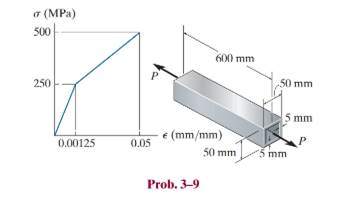
Determine the elongation of the square hollow bar when it is subjected to the axial force
Expert Solution & Answer
Want to see the full answer?
Check out a sample textbook solution
Students have asked these similar questions
The cross section of the rod in the picture is a circle with a diameter of 24 mm. The rod is pulled with a force of N = 20500 N, in addition to which a torque of T = 100 Nm acts. Determine the von Mises reference stress at point A on the outer surface of the rod. Note that it appears that the stress distributions caused by the normal force remain constant over the entire length of the beam! A plane stress state can be assumed at the point under consideration. Use units [N, mm] for calculations Please enter an answer to one decimal place. Do not round off the invoices in the intermediate stages, but only the final answer!
The cylindrical steel column has an outer diameter of 4 in. and inner diameter of 3.5 in. The column is separated
from the concrete foundation by a square bearing plate. The working compressive stress is 26 000 psi for the
column, and the working bearing stress is 1200 psi for concrete. Find the largest force P that can be applied to the
column. Express your answer in Ib.
4 in.
3.5 in.
4/4
7 in.
The vertical steel rod has a constant diameter of 32 mm and a length of 400 mm. is hanged from a rigid fixing. A mass is gently placed onto a collar which is attached to the lower end of the rod. The strain energy stored in the steel is 0.400 x 10-³.
If Esteet = 209 GPa,
1.1 Determine the gradually applied load and magnitude of the mass.
1.2 Calculate the maximum stress in the rod when gradually applied.
1.3 Determine the magnitude of the mass when the mass is suddenly applied.
1.4 Calculate the extension of the rod when suddenly applied.
Chapter 3 Solutions
Mechanics of Materials
Ch. 3.4 - Define a homogeneous material.Ch. 3.4 - Indicate the points on the stress-strain diagram...Ch. 3.4 - Define the modulus of elasticity E.Ch. 3.4 - At room temperature, mild steel is a ductile...Ch. 3.4 - Engineering stress and strain are calculated using...Ch. 3.4 - As the temperature increases the modulus of...Ch. 3.4 - A 100-mm-long rod has a diameter of 15 mm. If an...Ch. 3.4 - A bar has a length of 8 in. and cross-sectional...Ch. 3.4 - A 10-mm-diameter rod has a modulus of elasticity...Ch. 3.4 - The material for the 50-mm-long specimen has the...
Ch. 3.4 - The material for the 50-mm-long specimen has the...Ch. 3.4 - If the elongation of wire BC is 0.2 mm after the...Ch. 3.4 - Data taken from a stress-strain test for a ceramic...Ch. 3.4 - The stress-strain diagram for a steel alloy having...Ch. 3.4 - The stress-strain diagram for a steel alloy having...Ch. 3.4 - The stress-strain diagram for a steel alloy having...Ch. 3.4 - Determine the elongation of the square hollow bar...Ch. 3.4 - The stress-strain diagram for an aluminum alloy...Ch. 3.4 - The stress-strain diagram for an aluminum alloy...Ch. 3.4 - The stress-strain diagram for an aluminum alloy...Ch. 3.4 - A structural member in a nuclear reactor is made...Ch. 3.4 - The rigid pipe is supported by a pin at A and an...Ch. 3.4 - The rigid pipe is supported by a pin at A and an...Ch. 3.4 - Direct tension indicators are sometimes used...Ch. 3.4 - A tension test was performed on a magnesium alloy...Ch. 3.4 - The stress-strain diagram for a bone is shown and...Ch. 3.4 - The two bars are made of a material that has the...Ch. 3.4 - The two bars are made of a material that has the...Ch. 3.7 - A 100-mm-long rod has a diameter of 15 mm. If an...Ch. 3.7 - A solid circular rod that is 600 mm long and 20 mm...Ch. 3.7 - A 20-mm-wide block is firmly bonded to rigid...Ch. 3.7 - A 20-mm-wide block is bonded to rigid plates at...Ch. 3.7 - The acrylic plastic rod is 400mm long and 20mm in...Ch. 3.7 - The elastic portion of the stress-strain diagram...Ch. 3.7 - The elastic portion of the stress-strain diagram...Ch. 3.7 - The lap joint is connected together using a 1.25...Ch. 3.7 - The lap joint is connected together using a 1.25...Ch. 3.7 - Prob. 32PCh. 3.7 - The thin-walled tube is subjected to an axial...Ch. 3 - The elastic portion of the tension stress-strain...Ch. 3 - The elastic portion of the tension stress-strain...Ch. 3 - The rigid beam rests in the horizontal position on...Ch. 3 - The wires each have a diameter of 12 in., length...Ch. 3 - Prob. 5RPCh. 3 - diameter steel bolts. If the clamping force in...Ch. 3 - The stress-strain diagram for polyethylene, which...Ch. 3 - The pipe with two rigid caps attached to its ends...Ch. 3 - The 8-mm-diameter bolt is made of an aluminum...Ch. 3 - An acetal polymer block is fixed to the rigid...
Knowledge Booster


Learn more about
Need a deep-dive on the concept behind this application? Look no further. Learn more about this topic, mechanical-engineering and related others by exploring similar questions and additional content below.Similar questions
- A force P of 70 N is applied by a rider to thefront hand brake of a bicycle (P is the resultant of anevenly distributed pressure). As the hand brake pivots atA, a tension T develops in the 460-mm long brake cable(Ae = 1.075 mm2 ), which elongates by δ = 0.214 mm.Find the normal stress d and strain in the brake cable.arrow_forwardThe vertical shaft with a diameter of d = 20 mm is supported by a thrust collar that rests on a 21-mm-thick plate. The thrust collar is 16-mm thick. Assume that the load P causes a compressive stress of 190 MPa in the shaft. If the bearing stress between the thrust collar and the plate is limited to 35 MPa, determine the minimum outer diameter Dcollar that must be used for the thrust collar. Thrust collar area Plate Thrust collar d Dcollararrow_forwardThe head H is connected to the cylinder of a compressor using six 316-in. diameter steel bolts. If the clamping force in each bolt is 800 lb, determine the normal strain in the bolts. If sY = 40 ksi and Est = 2911032 ksi, what is the strain in each bolt when the nut is unscrewed so that the clamping force is released?arrow_forward
- The strain at a point is 780x10-6 in the x, 400x10-5 in the y and -500x10-6 in the z direction. Determine the stress state if the Young's modulus is 10,640 ksi and v = 0.33.arrow_forward2. The bar AC is supported by a pin at A and a cable that runs from B to E around the frictionless pully at D. If the allowable tensile stress oallow = 5.2 ksi for the cable, determine the required minimum diameter (inch) of the cable. The cylinder (connected at C) weighs 890 lb. Neglect weight and thickness of the bar AC. D 4 3 A C 5 ft 5 ft -4 ft 890 lbarrow_forwardThe uniform 300-lb bar AB carries a 500-lb vertical force at A. The bar is supported by a pin at B and the 0:5-in. diameter cable CD. Find the stress in the cable. 4 ft A 3 ft 3 ft B. 500 Ibarrow_forward
- The material for the 50-mm-long specimen has the stress–strain diagram shown. If P = 150 kN is applied and then released, determine the permanent elongation of the specimen.arrow_forwardA steel wire 5 m long hanging vertically supports a weight of 1200 kN. Determine the required wire diameter if the stress is limited to 140 MPa and the total elongation must not exceed 4 mm. Neglect the width of the wire and assume E=200 GPa.arrow_forwardDetermine the change in length, width and thickness of steel bar which is 4m long, 30mm wide and 20mm thick and is subjected to an axial pull of 30 kN in the direction of length. Take E = 200 GPa and poison's ratio of 0.3. Also determine the volumetric strain and change in volume.arrow_forward
- Two fully loaded tractor trailers travel over the bridge putting substantial loading on the structure. As they pass over the middle of the bridge, one of the vertical supporting pillars, which is fixed at its bottom, deforms as shown below. The weight of the trucks causes point T to move to point T'—a distance of 2.5 cm along the x-axis. If the pillar has an original height of 27 m , find the shear strain at point T.arrow_forwardQuestion 3 Determine the elongation of the square hollow bar when it is subjected to the axial force P = 100 kN, find the permanent elongation of the bar. The bar is made of a metal alloy having a stress-strain diagram which can be approximated as shown. o (MPa) 500 600 mm P 50 mm 250 5 mm e (mm/mm) 0.00125 0.05 50 mm ´5 mm a. Find the stress (MPa) of the bar. b. Find the permanent elongation (mm) of the bar.arrow_forwardThe rigid lever arm is supported by two A-36 steel wires having the same diameter of 4 mm. If a force of P = 3 kN is applied to the handle, determine the force developed in both wires and their corresponding elongations. Consider A-36 steel as an elastic perfectly plastic material.arrow_forward
arrow_back_ios
SEE MORE QUESTIONS
arrow_forward_ios
Recommended textbooks for you
 Elements Of ElectromagneticsMechanical EngineeringISBN:9780190698614Author:Sadiku, Matthew N. O.Publisher:Oxford University Press
 Mechanics of Materials (10th Edition)Mechanical EngineeringISBN:9780134319650Author:Russell C. HibbelerPublisher:PEARSON
 Thermodynamics: An Engineering ApproachMechanical EngineeringISBN:9781259822674Author:Yunus A. Cengel Dr., Michael A. BolesPublisher:McGraw-Hill Education
 Control Systems EngineeringMechanical EngineeringISBN:9781118170519Author:Norman S. NisePublisher:WILEY
 Mechanics of Materials (MindTap Course List)Mechanical EngineeringISBN:9781337093347Author:Barry J. Goodno, James M. GerePublisher:Cengage Learning
 Engineering Mechanics: StaticsMechanical EngineeringISBN:9781118807330Author:James L. Meriam, L. G. Kraige, J. N. BoltonPublisher:WILEY
Elements Of Electromagnetics
Mechanical Engineering
ISBN:9780190698614
Author:Sadiku, Matthew N. O.
Publisher:Oxford University Press
Mechanics of Materials (10th Edition)
Mechanical Engineering
ISBN:9780134319650
Author:Russell C. Hibbeler
Publisher:PEARSON
Thermodynamics: An Engineering Approach
Mechanical Engineering
ISBN:9781259822674
Author:Yunus A. Cengel Dr., Michael A. Boles
Publisher:McGraw-Hill Education
Control Systems Engineering
Mechanical Engineering
ISBN:9781118170519
Author:Norman S. Nise
Publisher:WILEY
Mechanics of Materials (MindTap Course List)
Mechanical Engineering
ISBN:9781337093347
Author:Barry J. Goodno, James M. Gere
Publisher:Cengage Learning
Engineering Mechanics: Statics
Mechanical Engineering
ISBN:9781118807330
Author:James L. Meriam, L. G. Kraige, J. N. Bolton
Publisher:WILEY
Strain energy and strain energy density introduced; Author: Engineer4Free;https://www.youtube.com/watch?v=m14sqLGg4BQ;License: Standard youtube license