
Concept explainers
Videos
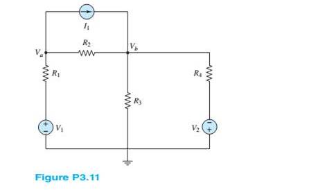
Use nodal analysis in the circuit of Figure P3.11 to find
Want to see the full answer?
Check out a sample textbook solution
Chapter 3 Solutions
Principles and Applications of Electrical Engineering


- Refer to the given circuit below. Using Superposition Theorem, determine the percent contribution of E₁ to the current through R3 (lbc)- R3E1 % contribution = x 100 R3E1+1R3E2+¹R31 R1 R2 R3 R4 E₁ E2 T 8 Ω 6Q 4Q 7 V 11 V 5 A R₂ C ΤΩ R₁ E₁ a b R3 RA E₂arrow_forwardRefer to the given circuit below. Using Superposition Theorem, determine the percent contribution of I to the current through R3 (lbc). IR31 % contribution = x 100 1 +1 +1 R3E1 "R3E2 R3 R4 E1 E2 I 6Q 1Q 9 V 7V 3A a R31 R1 2Q R1 R2 1Q E₁ R2 C b R3 R4 E2arrow_forward3b For the circuit in Figure Q3(b), solve for Ix, Iy and Vz using superposition method.arrow_forward
- b) For the circuit shown in Figure Q3b: i) Define coupling coefficient. ii) Find the voltage, Vx. j3 2 + Vx -A j4 Q j2 Q 520° V j5 Q j7 Q j1 0 12 12 Q Figure Q3barrow_forwardO Given the information appearing in the Figure, Fird the level of resistance for Ri e R3. RI 3 o 14V Rgarrow_forward3.40 Find Vi and V in the circuit shown in Figure P340. FIGURE P3.40 2 kn R2 V2 4 kn 2000 i 5 V 3 kn 2.5 k 45arrow_forward
- (b) Prove the circuit in Figure Q.5 can perform the operation of adder/subtractor by completing Table Q.5. -Sub FA FA FA FA Figure Q.5 Table Q.5 B[3:0] Sub A[3:0] C4 S[3:0] Operation 0111 1000 1 0111 1000arrow_forwardPROBLEM 4. In the circuit below, R3 = 10 k2. Calculate the steady-state voltage across each circuit element. -20V R3 www R2 -5kQ C1 :6μF R1 >8kQarrow_forwardProblem F3 Design a value for R,, R, and Res such that 0.5 mA can be delivered to loads up to 18k Veco Vcc oL Rcs R1 Vcco- V+ R2 Vcc / -Vcc Q1 V- 15V /-15V R2 Lo-Vcc RLoad +arrow_forward
- Refer to the given circuit below. Using Superposition Theorem, determine the percent contribution of E₁ to the current through R3 (lbc)- 1 R3E1 % contribution = - x 100 R3E2 + 1 R1 R2 R3 R4 E₁ E2 I 3 Ω 70 4 Ω 3 Ω 7 V 8 V 5 A I R3E1 +1 R31 + R₁ E₁ a ↑ R₂ C b R3 R4 E₂ +arrow_forward3.1 Evaluate the following circuit and determine the following: Given: C1=10uF, C2=20UF, C3= 13UF, C4= 15uF, C5= 9uF, V=300 V C2 C1 C3 C5 C4arrow_forwardConsider the series-parallel circuit shown in the figure below with various multimeters connected in the circuit. Assum that XMM1 has been configured in ammeter mode, and XMM2 has been configured in voltmeter mode. XMM1 R1 1kQ XMM2 R2 R3 V1 1kQ 1kQ 12V 3.1: Redraw the circuit replacing XMM1 and XMM2 by their equivalent circuit models 3.2: Assume that XMM2 was incorrectly configured in ammeter mode. Redraw the equivalent circuit from 3.1 and compute the current that would be measured by the ammeter in this scenario. Hil-arrow_forward
 Introductory Circuit Analysis (13th Edition)Electrical EngineeringISBN:9780133923605Author:Robert L. BoylestadPublisher:PEARSON
 Delmar's Standard Textbook Of ElectricityElectrical EngineeringISBN:9781337900348Author:Stephen L. HermanPublisher:Cengage Learning
 Programmable Logic ControllersElectrical EngineeringISBN:9780073373843Author:Frank D. PetruzellaPublisher:McGraw-Hill Education
 Fundamentals of Electric CircuitsElectrical EngineeringISBN:9780078028229Author:Charles K Alexander, Matthew SadikuPublisher:McGraw-Hill Education
 Electric Circuits. (11th Edition)Electrical EngineeringISBN:9780134746968Author:James W. Nilsson, Susan RiedelPublisher:PEARSON
 Engineering ElectromagneticsElectrical EngineeringISBN:9780078028151Author:Hayt, William H. (william Hart), Jr, BUCK, John A.Publisher:Mcgraw-hill Education,