
Introductory Circuit Analysis (13th Edition)
13th Edition
ISBN: 9780133923605
Author: Robert L. Boylestad
Publisher: PEARSON
expand_more
expand_more
format_list_bulleted
Related questions
Question
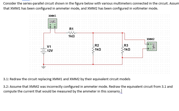

Transcribed Image Text:Consider the series-parallel circuit shown in the figure below with various multimeters connected in the circuit. Assum
that XMM1 has been configured in ammeter mode, and XMM2 has been configured in voltmeter mode.
XMM1
R1
1kQ
XMM2
R2
R3
V1
1kQ
1kQ
12V
3.1: Redraw the circuit replacing XMM1 and XMM2 by their equivalent circuit models
3.2: Assume that XMM2 was incorrectly configured in ammeter mode. Redraw the equivalent circuit from 3.1 and
compute the current that would be measured by the ammeter in this scenario.
Hil-
Expert Solution
This question has been solved!
Explore an expertly crafted, step-by-step solution for a thorough understanding of key concepts.

This is a popular solution

Trending nowThis is a popular solution!

Step by stepSolved in 3 steps with 3 images

Knowledge Booster


Learn more about
Need a deep-dive on the concept behind this application? Look no further. Learn more about this topic, electrical-engineering and related others by exploring similar questions and additional content below.Similar questions
- Based on electric circuit shown in Figure 2. Determine whether the LED 1 and LED 2 is “ON" or "OFF" for V1 = 2V and V1 = 3.5V if for both LEDS are silicon LED. Explain the answer given. V1 OUT R1 OPAMP 100kN V2 LED 1 LED 2 4Vdc R2 500kn Figure 2: Op-Amp circuit with LEDarrow_forwardThe source voltage of the circuit is 5V and the break down voltage for the Zener diode is 5.2V then the voltage across resistor will be ??arrow_forwardA circuit contains a diode in series with a 500 ohm resistor. The diode is oriented to all current towards the positive side of the power source. Plot IV curvearrow_forward
- Referring to Figure , you measure the potential at the connection points R1 and R2 of 3 V. If you get a potential of 0 V at the connection point of the diode and R3, what can you do explain about the condition of the circuit?arrow_forward2. Find out the VOC and the fill factors (FFs) for solar cells with an Io of 10-18 A/cm2 for the following cases. a. Jsc =10 mA/cm2 and Rsh (shunt or parallel resistance)=1 k Ohm cm2b. Jsc =100 mA/cm2 and Rsh (shunt or parallel resistance)=100 k Ohm cm2arrow_forward
arrow_back_ios
arrow_forward_ios
Recommended textbooks for you
- Introductory Circuit Analysis (13th Edition)Electrical EngineeringISBN:9780133923605Author:Robert L. BoylestadPublisher:PEARSON
 Delmar's Standard Textbook Of ElectricityElectrical EngineeringISBN:9781337900348Author:Stephen L. HermanPublisher:Cengage Learning
 Programmable Logic ControllersElectrical EngineeringISBN:9780073373843Author:Frank D. PetruzellaPublisher:McGraw-Hill Education
  Fundamentals of Electric CircuitsElectrical EngineeringISBN:9780078028229Author:Charles K Alexander, Matthew SadikuPublisher:McGraw-Hill Education
 Electric Circuits. (11th Edition)Electrical EngineeringISBN:9780134746968Author:James W. Nilsson, Susan RiedelPublisher:PEARSON
 Engineering ElectromagneticsElectrical EngineeringISBN:9780078028151Author:Hayt, William H. (william Hart), Jr, BUCK, John A.Publisher:Mcgraw-hill Education,
Introductory Circuit Analysis (13th Edition)
Electrical Engineering
ISBN:9780133923605
Author:Robert L. Boylestad
Publisher:PEARSON
Delmar's Standard Textbook Of Electricity
Electrical Engineering
ISBN:9781337900348
Author:Stephen L. Herman
Publisher:Cengage Learning
Programmable Logic Controllers
Electrical Engineering
ISBN:9780073373843
Author:Frank D. Petruzella
Publisher:McGraw-Hill Education
Fundamentals of Electric Circuits
Electrical Engineering
ISBN:9780078028229
Author:Charles K Alexander, Matthew Sadiku
Publisher:McGraw-Hill Education
Electric Circuits. (11th Edition)
Electrical Engineering
ISBN:9780134746968
Author:James W. Nilsson, Susan Riedel
Publisher:PEARSON
Engineering Electromagnetics
Electrical Engineering
ISBN:9780078028151
Author:Hayt, William H. (william Hart), Jr, BUCK, John A.
Publisher:Mcgraw-hill Education,