
Principles and Applications of Electrical Engineering
6th Edition
ISBN: 9780073529592
Author: Giorgio Rizzoni Professor of Mechanical Engineering, James A. Kearns Dr.
Publisher: McGraw-Hill Education
expand_more
expand_more
format_list_bulleted
Concept explainers
Videos
Textbook Question
Chapter 3, Problem 3.79HP
The non-linear diode in Figure P3.79 has the i-v character is tic shown. Assume:
Determine the voltage across and the current through the diode.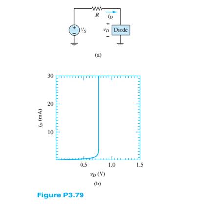
Expert Solution & Answer
Want to see the full answer?
Check out a sample textbook solution
Students have asked these similar questions
Given the following circuit with VDD=
9.2 V, R=2.3 k2, then the current Iis:
Use the CVD model for the diode, with
VD = 0.65 V.
I
VDD
a. 0.004000 A
O b. 3.717391 A
OC. 0 A
d. 4.000000 A
e. 0.003717 A
R
+
VD
-
60 V
D1
D2
2 kohm
DA
D3
-60 V
Assume that an input signal is applied to the circuit given above, as shown in the figure next to
it. Accordingly, answer the following questions. The diodes used are silicon diodes, their
operating voltages are 0.7 volts, and can be omitted because their resistance is very small.
Calculate V p-out( Vm ) for this circuit.
60 V
D1
D2
2 kohm
D4
D3
-60 V
Assume that an input signal is applied to the circuit given above, as shown in the figure next to
it. Accordingly, answer the following questions. The diodes used are silicon diodes, their
operating voltages are 0.7 volts, and can be omitted because their resistance is very small.
What are the diodes/diodes that are active in a positive half-loop? Please type.
Chapter 3 Solutions
Principles and Applications of Electrical Engineering
Ch. 3 - Use node voltage analysis to find the voltages V1...Ch. 3 - Use node voltage analysis to find the voltages V1...Ch. 3 - Using node voltage analysis in the circuit of...Ch. 3 - Using node voltage analysis in the circuit of...Ch. 3 - In the circuit shown in Figure P3.5, the mesh...Ch. 3 - In the circuit shown in Figure P3.5, the source...Ch. 3 - Use nodal analysis in the circuit of Figure P3.7...Ch. 3 - Use mesh analysis in the circuit of Figure P3.7 to...Ch. 3 - Use nodal analysis in the circuit of Figure P3.9...Ch. 3 - Use nodal analysis in the circuit of Figure P3.10...
Ch. 3 - Use nodal analysis in the circuit of Figure P3.11...Ch. 3 - Find the power delivered to the load resistor R0...Ch. 3 - For the circuit of Figure P3.13, write the nodee...Ch. 3 - Using mesh analysis, find the currents i1 and i2...Ch. 3 - Using mesh analysis, find the currents i1 and i2...Ch. 3 - Using mesh analysis, find the voltage v across the...Ch. 3 - Using mesh analysis, find the currents I1,I2 and...Ch. 3 - Using mesh analysis. Find the voltage V across the...Ch. 3 - Prob. 3.19HPCh. 3 - For the circuit of Figure P3.20, use mesh analysis...Ch. 3 - In the circuit in Figure P3.21, assume the source...Ch. 3 - For the circuit of Figure P3.22 determine: a. The...Ch. 3 - Figure P3.23 represents a temperature measurement...Ch. 3 - Use nodal analysis on the circuit in Figure P3.24...Ch. 3 - Use mesh analysis to find the mesh currents in...Ch. 3 - Use mesh analysis to find the mesh currents in...Ch. 3 - Use mesh analysis to find the currents in Figure...Ch. 3 - Use mesh analysis to find V4 in Figure P3.28. Let...Ch. 3 - Use mesh analysis to find mesh currents in Figure...Ch. 3 - Use mesh analysis to find the current i in Figure...Ch. 3 - Use mesh analysis to find the voltage gain...Ch. 3 - Use nodal analysis to find node voltages V1,V2,...Ch. 3 - Use mesh analysis to find the currents through...Ch. 3 - Prob. 3.34HPCh. 3 - Prob. 3.35HPCh. 3 - Using the data of Problem 3.35 and Figure P3.35,...Ch. 3 - Prob. 3.37HPCh. 3 - Prob. 3.38HPCh. 3 - Use nodal analysis in the circuit of Figure P3.39...Ch. 3 - Prob. 3.40HPCh. 3 - Refer to Figure P3.10 and use the principle of...Ch. 3 - Use the principle of superposition to determine...Ch. 3 - Refer to Figure P3.43 and use the principle of...Ch. 3 - Refer to Figure P3.44 and use the principle of...Ch. 3 - Refer to Figure P3.44 and use the principle of...Ch. 3 - Prob. 3.46HPCh. 3 - Use the principle of super position to determine...Ch. 3 - Prob. 3.48HPCh. 3 - Use the principle of super position to determine...Ch. 3 - Use the principle of superposition to determine...Ch. 3 - Find the Thé venin equivalent of the network...Ch. 3 - Find the Thé venin equivalent of the network seen...Ch. 3 - Find the Norton equivalent of the network seen by...Ch. 3 - Find the Norton equivalent of the network between...Ch. 3 - Find the Thé venin equivalent of the network seen...Ch. 3 - Prob. 3.56HPCh. 3 - Find the Thé venin equivalent of the network seen...Ch. 3 - Find the Thé venin equivalent network seen by...Ch. 3 - Prob. 3.59HPCh. 3 - Prob. 3.60HPCh. 3 - Prob. 3.61HPCh. 3 - Find the Thé venin equivalent resistance seen...Ch. 3 - Find the Thé venin equivalent resistance seen by...Ch. 3 - Find the Thé venin equivalent network seen from...Ch. 3 - Find the Thé’cnin equivalent resistance seen by R3...Ch. 3 - Find the Norton equivalent of the network seen by...Ch. 3 - Find the Norton equivalent of the network seen by...Ch. 3 - Prob. 3.68HPCh. 3 - Find the Norton equivalent network between...Ch. 3 - Prob. 3.70HPCh. 3 - Prob. 3.71HPCh. 3 - Prob. 3.72HPCh. 3 - The Thé venin equivalent network seen by a load Ro...Ch. 3 - The Thévenin equivalent network seen by a load Ro...Ch. 3 - Prob. 3.75HPCh. 3 - Prob. 3.76HPCh. 3 - Many practical circuit elements are non-linear;...Ch. 3 - Prob. 3.78HPCh. 3 - The non-linear diode in Figure P3.79 has the i-v...Ch. 3 - Prob. 3.80HPCh. 3 - The non-linear device D in Figure P3.81 has the...Ch. 3 - Prob. 3.82HPCh. 3 - The so-called forward-bias i-v relationship for a...
Knowledge Booster


Learn more about
Need a deep-dive on the concept behind this application? Look no further. Learn more about this topic, electrical-engineering and related others by exploring similar questions and additional content below.Similar questions
- 60 V D1 D2 2 kohm D4 D3 -60 V Assume that an input signal is applied to the circuit given above, as shown in the figure next to it. Accordingly, answer the following questions. The diodes used are silicon diodes, their operating voltages are 0.7 volts, and can be omitted because their resistance is very small. What are the diodes/diodes active in the negative half-loop? Please type.arrow_forwardA diode circuit is given in the below figure, in which two diodes are connected in series and their saturation currents are Is1 =10-¹6 A and Is2 =10-¹4 A. If the applied source voltage is 1 V, calculate the currents IDI and ID2 and the voltage across each diode VDI and VD2. IDI Ī Vpl + D₂ VD2arrow_forwardFind the maximum zener current for the zener diode as shown in figure. Given, V₂=6V,R₂ = 1.522, R = 40022 20V IT R www IL RLarrow_forward
- uO 9:.0 A docs.google.com * ZAIN IQ l. Q3/B: Assume an ideal diode model for all the diodes in the circuit below. calculate voltages and currents through D1 and D2 9kQ 1N1199C R2 D1 18KQ 1N1199C D3 1N1199C V2 =12 V R3 1kQ R4 5kQ 1.22 V 11 mA 0.5 A O VD1 ID1 VD2 ID2 صفحة 4 من 6arrow_forwardUsing the ideal diode model, find the output voltage for the input voltage of the following circuit and graph it in detail. (a) (b) R₁ D₁ www ww R3 D2 (a) R₁ D₁ www + + D2 R2 vo Vo R₂ (b)arrow_forward1. Half-wave battery charger. Consider the battery charging circuit in Figure. with Vm= 20V, R= 10Nand VB= 14V. Find the peak current assuming an ideal diode. Current limiting resistor R + Vsin(@x) i(t) VBarrow_forward
- 0:- Consider the circuit in Figure a) What type of circuit is this? b) Find and Sketch the voltage waveform across RL, assume the diodes are practical. c) If 100uf capacitor parallel with the resistor, calculate the ripple is connected factor I O o Darrow_forwardQ3: - Draw the voltage and current waveform for the circuit given below. Then find the output efficiency and the required PIV. Assume the diode is ideal. Vo Vin=40sinwt (volt) f=50H2 R=0.7KOarrow_forward3. Given a circuit in figure 3.1. A Zener diode is connected as shown in the Figure. The Zener voltage is 7.2 V and the load current is to change from 12 to 100 mA. Calculate the value of series resistance R to maintain a voltage of 7.2 V across the load. The input voltage is constant at 12 V and the minimum Zener current is 10 mA. IL I R Iz Eo RL Vz E, = 12 VI Figure 3.1 stabilizer circuit.arrow_forward
- Find the voltages at V1 and V2. Consider as a practical diode. 6V +V 10k Si Si 5k +v3Varrow_forwardHow do I calculate the dynamic resistance of a zener diode with the following set of values given please? The circuit in figure is the circuit in question I am trying to solve this for please. Vin(DC) = 10V vin(ac) = 0.05sin(wt) Vz(voltage of diode) = 4.5V R1 = 1000 ohmsarrow_forward4. For the circuit shown in the figure below uses a transformer of 230V/12V-0-12V and all diodes are Ge find the following, RL-3.3k2. The name of the circuit is ........ Current through the load is............The DC output voltage is............ Draw the input & output wave forms ✈ ellel eetee CT D₂ DE www R₂arrow_forward
arrow_back_ios
SEE MORE QUESTIONS
arrow_forward_ios
Recommended textbooks for you
 Introductory Circuit Analysis (13th Edition)Electrical EngineeringISBN:9780133923605Author:Robert L. BoylestadPublisher:PEARSON
 Delmar's Standard Textbook Of ElectricityElectrical EngineeringISBN:9781337900348Author:Stephen L. HermanPublisher:Cengage Learning
 Programmable Logic ControllersElectrical EngineeringISBN:9780073373843Author:Frank D. PetruzellaPublisher:McGraw-Hill Education
 Fundamentals of Electric CircuitsElectrical EngineeringISBN:9780078028229Author:Charles K Alexander, Matthew SadikuPublisher:McGraw-Hill Education
 Electric Circuits. (11th Edition)Electrical EngineeringISBN:9780134746968Author:James W. Nilsson, Susan RiedelPublisher:PEARSON
 Engineering ElectromagneticsElectrical EngineeringISBN:9780078028151Author:Hayt, William H. (william Hart), Jr, BUCK, John A.Publisher:Mcgraw-hill Education,
Introductory Circuit Analysis (13th Edition)
Electrical Engineering
ISBN:9780133923605
Author:Robert L. Boylestad
Publisher:PEARSON
Delmar's Standard Textbook Of Electricity
Electrical Engineering
ISBN:9781337900348
Author:Stephen L. Herman
Publisher:Cengage Learning
Programmable Logic Controllers
Electrical Engineering
ISBN:9780073373843
Author:Frank D. Petruzella
Publisher:McGraw-Hill Education
Fundamentals of Electric Circuits
Electrical Engineering
ISBN:9780078028229
Author:Charles K Alexander, Matthew Sadiku
Publisher:McGraw-Hill Education
Electric Circuits. (11th Edition)
Electrical Engineering
ISBN:9780134746968
Author:James W. Nilsson, Susan Riedel
Publisher:PEARSON
Engineering Electromagnetics
Electrical Engineering
ISBN:9780078028151
Author:Hayt, William H. (william Hart), Jr, BUCK, John A.
Publisher:Mcgraw-hill Education,
How do Solar cells work?; Author: Lesics;https://www.youtube.com/watch?v=L_q6LRgKpTw;License: Standard Youtube License