
Concept explainers
Videos
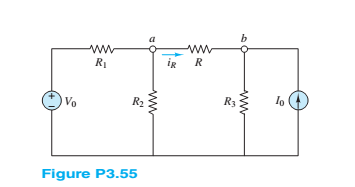
Find the Thé venin equivalent of the network seen by R in Figure P3.55, and use the result to compute the current
Want to see the full answer?
Check out a sample textbook solution
Chapter 3 Solutions
Principles and Applications of Electrical Engineering


- Q3. The circuit to study is shown in figure below, where V1 = 100/0° V, V2 = 50/60° V, and R₁ = 3 Q, R₂ = 50, R3 = 2, R4 = 50, R5 = 50, L5 = 12.8 mH, L6 = 6.4 mH ,C₂= 796µF and C3=796uF assume f=50Hz V1 R1 R5 R2 + Vx & L5 Monote R3 L6 mo V2 C3 R4 a) Apply the mesh current method to obtain a complete set of circuit equations, presenting your answer in matrix form; b) Compute the potential across and the current flowing through the L6 elements.arrow_forwardQ3) For the network shown in the figure below, determine the following: a) fe b) Zinl and Zin2 c) Zo1 and Zo2 d) Avı, Av2, and AVT +20 V 6.8 kQ 30 ka 6.8 ka 30 ka 0.5 F 0.5 uF P-150 B- 150 1.5 ka 50 uF 1.5 ka 50 uFarrow_forwardc) What is the name and one of the advantages and one of the disadvantages of the current mirror shown in Figure Q3c? IREF OUT = ID2 VB M3 X M1 Figure Q3c M4 Y M2arrow_forward
- b) For the circuit shown in Figure Q3b: i) Define coupling coefficient. ii) Find the voltage, Vx. j3 2 + Vx -A j4 Q j2 Q 520° V j5 Q j7 Q j1 0 12 12 Q Figure Q3barrow_forwardfind Rt, It, Pt, P1, P2, P3P4,P5,P6arrow_forwardRefer to the given circuit below. Using Superposition Theorem, determine the percent contribution of E₁ to the current through R3 (lbc)- R3E1 % contribution = x 100 R3E1+1R3E2+¹R31 R1 R2 R3 R4 E₁ E2 T 8 Ω 6Q 4Q 7 V 11 V 5 A R₂ C ΤΩ R₁ E₁ a b R3 RA E₂arrow_forward
- Q3: Suppose that the components of the circuit shown in figure below have the following values: RI= SkD, R2= 9kΩ, R3-10kΩ , R4-5kΩ, R5-10kΩ, R6-9k Ω. The voltage across AB is measured by a voltmeter whose internal resistance is 95k2. What is the measurement error caused by the resistance of the measuring instrument? R3 Rs RM Ri SMA Fo Em Ry Barrow_forward(b) In the circuit shown in Figure Q3(b), (i) Find the value of open circuit voltage, VTH and equivalent resistance, Rth at terminal a-b. (ii) Draw the Thevenin equivalent circuit at terminal a-b. 5000 a 6mA 5002 5V 4002 b Figure Q3(b)arrow_forwardRefer to the given circuit below. Using Superposition Theorem, determine the percent contribution of I to the current through R3 (lbc). IR31 % contribution = x 100 1 +1 +1 R3E1 "R3E2 R3 R4 E1 E2 I 6Q 1Q 9 V 7V 3A a R31 R1 2Q R1 R2 1Q E₁ R2 C b R3 R4 E2arrow_forward
- (b) Prove the circuit in Figure Q.5 can perform the operation of adder/subtractor by completing Table Q.5. -Sub FA FA FA FA Figure Q.5 Table Q.5 B[3:0] Sub A[3:0] C4 S[3:0] Operation 0111 1000 1 0111 1000arrow_forward3.16 plz solve and explain this examplestep by step plz avoid direct solutionarrow_forwardWrite the Loop-current equations for the circuit below. Then, determine the values of i, iz and i3. 50 10 30 V 15 V wwarrow_forward
 Introductory Circuit Analysis (13th Edition)Electrical EngineeringISBN:9780133923605Author:Robert L. BoylestadPublisher:PEARSON
 Delmar's Standard Textbook Of ElectricityElectrical EngineeringISBN:9781337900348Author:Stephen L. HermanPublisher:Cengage Learning
 Programmable Logic ControllersElectrical EngineeringISBN:9780073373843Author:Frank D. PetruzellaPublisher:McGraw-Hill Education
 Fundamentals of Electric CircuitsElectrical EngineeringISBN:9780078028229Author:Charles K Alexander, Matthew SadikuPublisher:McGraw-Hill Education
 Electric Circuits. (11th Edition)Electrical EngineeringISBN:9780134746968Author:James W. Nilsson, Susan RiedelPublisher:PEARSON
 Engineering ElectromagneticsElectrical EngineeringISBN:9780078028151Author:Hayt, William H. (william Hart), Jr, BUCK, John A.Publisher:Mcgraw-hill Education,