
Control Systems Engineering
7th Edition
ISBN: 9781118170519
Author: Norman S. Nise
Publisher: WILEY
expand_more
expand_more
format_list_bulleted
Concept explainers
Videos
Textbook Question
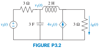
Chapter 3, Problem 2P
Represent the electrical network shown in Figure P3.2 in state space, where iR(t) is the output. [Section: 3.4]
Expert Solution & Answer

Trending nowThis is a popular solution!

Students have asked these similar questions
3. In this problem, you are going to analyze the dynamics of a rotational mechanical system
shown in Figure below (this is also covered in Lecture Notes #3 of M. Mert Ankarali [1]).
In this system input the external torque t(t), and output is the angular velocity of the load
wL(t).
JR
WR
OR
K
JL
OL WL
T
DL
DR
The state-space representation of this system is provided in the Lecture Notes #3 [1].
Find the transfer function of the dynamical system.
Find another (minimal) state-space representation for the system.
38. Given the rotational system shown in Figure P2.24,
find the transfer function, G(s) = 06(s)/01(s).
[Section: 2.7]
equations:
QB: Obtain the transfer function of system defined by the following state space
Hi
0 4 8 [x₁
0 8 5
X2 +
-10-30-20x330/u
[123]
[x1
Y=[1 2 0] X₂
X3
snp-you
tvave
Chapter 3 Solutions
Control Systems Engineering
Ch. 3 - Prob. 1RQCh. 3 - State an advantage of the transfer function...Ch. 3 - Define state variables.Ch. 3 - Define state.Ch. 3 - Define state vector.Ch. 3 - Define state space.Ch. 3 - What is required to represent a system in state...Ch. 3 - 8. An eighth-order system would be represented in...Ch. 3 - If the state equations are a system of first-order...Ch. 3 - Prob. 10RQ
Ch. 3 - What factors influence the choice of state...Ch. 3 - What is a convenient choice of state variables for...Ch. 3 - If an electrical network has three energy-storage...Ch. 3 - Prob. 14RQCh. 3 - Prob. 1PCh. 3 - Represent the electrical network shown in Figure...Ch. 3 - Prob. 3PCh. 3 - Represent the system shown in Figure P3.4 in state...Ch. 3 - Represent the rotational mechanical system shown...Ch. 3 - Represent the system shown in Figure P3.7 in state...Ch. 3 - 8. Show that the system of Figure 3.7 in the text...Ch. 3 - Find the state-space representation in...Ch. 3 - MATLAB ML 10. Repeat Problem 9 using MATLAB....Ch. 3 - For each system shown in Figure P3.9, write the...Ch. 3 - MATLAB ML
12. Repeat Problem 11 using MATLAB....Ch. 3 - 13. Represent the following transfer function in...Ch. 3 - Find the transfer function G(s) = Y(s)/R(s) for...Ch. 3 - MATLAB ML
15. Use MATLAB to find the transfer...Ch. 3 - 17. A missile in flight, as shown in Figure P3.10,...Ch. 3 - Given the dc servomotor and load shown in Figure...Ch. 3 - Prob. 20PCh. 3 - Prob. 23PCh. 3 - Experiments to identify precision grip dynamics...Ch. 3 - State-space representations are, in general, not...Ch. 3 - Figure P3.16 shows a schematic description of the...Ch. 3 - Prob. 28PCh. 3 - A single-pole oil cylinder valve contains a spool...Ch. 3 - Figure P3.17 shows a free-body diagram of an...Ch. 3 - 33. Parabolic trough collector. A transfer...
Knowledge Booster


Learn more about
Need a deep-dive on the concept behind this application? Look no further. Learn more about this topic, mechanical-engineering and related others by exploring similar questions and additional content below.Similar questions
- This question asks for matrix form and NOT state space, but I don't understand what the difference between the two are.arrow_forwardExplain the state space functionarrow_forwardConsider the following state space system 1 B = 1 C =[1 0] D=[0] -5 -6 1- Check the controllability of the system. 2- Check the observability of the systemarrow_forward
- on of nd 25. For the system shown in Figure P4.7, do the following: [Section: 4.6] a. Find the transfer function G(s) = X(s)/F(s). b. Find , n, %OS, Ts, Tp, Tr, and Cfinal for a unit-step input. 20 N/m oooo 2 N-s/m 5 kg x(1) FIGURE P4.7 f(1)arrow_forwardFind a state space representation of the network shown below when the output is the displacement on m Let my = 2 kg, m₁ = 4kg, F = 10 N, b₁ = 1 Ns/m, b2 = 2 Ns/m, k₁ = 2 N/m, and k2 = 4 N/m, Force of material placed in truck bed M Truck vehicle mass Shock absorber www www A Tirearrow_forward32. For the rotational mechanical system with gears shown in Figure P2.18, find the transfer function, G(s) = 03(s)/T(s). The gears have inertia and bear- ing friction as shown. [Section: 2.7] T(t) to |N1 小D N2 N3 2, D2 Jz, D3 03(1) N4 J4. D4 J5. D5 FIGURE P2.18 sairarrow_forward
- Consider the state space representation of the following system [6]-[2][]+8-0 X2 (1) y()=[11][26] y(t) = [1 X2 u(t) Find x(t) and y(t) of this systems by u(t)= unit step function. =[7] x(0) = Xo =arrow_forwardLook at the block diagram for the dynamic model of the hydraulically actuated system in Fig where: km = 0.2 J = 0.1 m = 5 k₂ = 3 L₂ = 2 KAP = 4 *BÖH Lu da K₁ W *ÖDDÖDDÖD D Km/J X4 QmJ/Km K₁pJ 1. Determine the controllability and observability for this system d₂ X3 X₂ Aarrow_forwardProblem 1: Write the transfer function of the systems. Problem 2: Write the differential equation and state space equation describing the following system. Please answer both the problems.arrow_forward
- 28. Find the transfer function, G(s) = X1(s)/F(s), for the translational mechanical system shown in Figure P2.13. [Section: 2.5] 2 N-s/m X3(1) 2 N-s/m (1)'x- [4 kg 2 N-s/m 6 N/m 6 N/m 4 kg 0000 4 kg "Frictionless FIGURE P2.13 USE MATRIX METHODarrow_forward2. Assume a 2 DOF rigid body with a rigid bar, which is supported by a two-spring damper :3k4, m = supports. Inertia and length of the rigid body are I = 10kg and L= 4m. (a) Derive the mathematical model of the system in variable form (b) Write the state space representation of the above system. (c) k₁= k₂ = 800N.m and c₁ = C₂ = 350N.s/m Develop a simulink model and plot all the system response for input y = sin(wt), where w 1 rad = S (d) k₁ 400v, k₂ 800N.m and c₁ = 175N.s/m, c₂ 350N.s/m Develop a simulink model and plot all the system response for input y = sin(wt), where w = = 1 rad 8 - L/4 k₁,c m, I L/4 k₂,c y = sin wtarrow_forwardFor the following state-space representation,define the:– State Vector– System Matrix– Feedforward Matrix– Input Matrix & Input Vector– Output Matrix & Output Vectorarrow_forward
arrow_back_ios
SEE MORE QUESTIONS
arrow_forward_ios
Recommended textbooks for you
 Elements Of ElectromagneticsMechanical EngineeringISBN:9780190698614Author:Sadiku, Matthew N. O.Publisher:Oxford University Press
 Mechanics of Materials (10th Edition)Mechanical EngineeringISBN:9780134319650Author:Russell C. HibbelerPublisher:PEARSON
 Thermodynamics: An Engineering ApproachMechanical EngineeringISBN:9781259822674Author:Yunus A. Cengel Dr., Michael A. BolesPublisher:McGraw-Hill Education
 Control Systems EngineeringMechanical EngineeringISBN:9781118170519Author:Norman S. NisePublisher:WILEY
 Mechanics of Materials (MindTap Course List)Mechanical EngineeringISBN:9781337093347Author:Barry J. Goodno, James M. GerePublisher:Cengage Learning
 Engineering Mechanics: StaticsMechanical EngineeringISBN:9781118807330Author:James L. Meriam, L. G. Kraige, J. N. BoltonPublisher:WILEY
Elements Of Electromagnetics
Mechanical Engineering
ISBN:9780190698614
Author:Sadiku, Matthew N. O.
Publisher:Oxford University Press
Mechanics of Materials (10th Edition)
Mechanical Engineering
ISBN:9780134319650
Author:Russell C. Hibbeler
Publisher:PEARSON
Thermodynamics: An Engineering Approach
Mechanical Engineering
ISBN:9781259822674
Author:Yunus A. Cengel Dr., Michael A. Boles
Publisher:McGraw-Hill Education
Control Systems Engineering
Mechanical Engineering
ISBN:9781118170519
Author:Norman S. Nise
Publisher:WILEY
Mechanics of Materials (MindTap Course List)
Mechanical Engineering
ISBN:9781337093347
Author:Barry J. Goodno, James M. Gere
Publisher:Cengage Learning
Engineering Mechanics: Statics
Mechanical Engineering
ISBN:9781118807330
Author:James L. Meriam, L. G. Kraige, J. N. Bolton
Publisher:WILEY
Ch 2 - 2.2.2 Forced Undamped Oscillation; Author: Benjamin Drew;https://www.youtube.com/watch?v=6Tb7Rx-bCWE;License: Standard youtube license