
Videos
Figure P3.17 shows a free-body diagram of an inverted pendulum, mounted on a cart with a mass, M. The pendulum has a point mass, m, concentrated at the upper end of a rod with zero mass, a length, I, and a frictionless hinge. A motor drives the cart, applying a horizontal force, u(t). A gravity force, mg, acts on m at all times. The pendulum angle relative to the y-axis,
However, since x0= 0 and u0= 0, then let:
where
Assuming the output to be the horizontal position of
Given that: M = 2.4 kg, m = 0.23 kg, MATLAB ML l = 0.36 m, g = 9.81 m/s2, use MATLAB to ?nd the transfer function, G(s) = Y(s)/U(s) = Xm(s)/U(s).
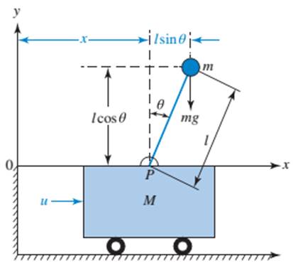
FIGURE P3.17 Motor-driven inverted pendulum can system15
Want to see the full answer?
Check out a sample textbook solution
Chapter 3 Solutions
Control Systems Engineering


- 30. For each of the rotational mechanical systems shown in Figure P2.16, write, but do not solve, the equations of motion. [Section: 2.6] O(1) 8 N-m-s/rad A I N-m-s/rad O 3 kg-m? 9 N-m/rad 3 N-m/rad (a)arrow_forwardFour masses A, B, C and D as shown below are to be completely balanced. Find the followings: v The axial distance between the planes of rotation of B and C(mm) v The magnitude and angular position of mass of Mp{Kg) v The angle between mass A and D (LAOD-7degree) A B. D 80 Mp Mass (kg) Radius 125 150 100 (mem) 50 60 200 120 A B 115mmarrow_forwardShown below is a system in which a cable from block A of mass m=73-kg passes Mass M 2r - MR Mass = m through around a pully of mass m, and radius r=10-cm, and is wrapped around the a drum of mass M=1.2-kg. Let the pulley and 1, = mR %3D Mass = m A the drum have moment of inertia lo=mR, where m is the mass and Ris the radius. (a) draw the free body diagram of each body (b) write the equations of motion (C)Determine the acceleration of block A Answerarrow_forward
- Problem Derive the differential equation governing the motion of the one degree-of-freedom system by applying the appropriate form(s) of Newton's laws to the appropriate free-body diagrams. Use the generalized coordinate shown in Figure P2.427. Linearize nonlinear differential equations by assuming small displacements. 2k - Rigid massless link Identical slender bars of mass m, length L. FIGURE P 2.47arrow_forward2.1 Figure P2.1 shows a single-mass translational mechanical system. Both springs are undeflected when z = 0 and fa(t) = o. Derive the mathematical model of the mechanical system. Figure P2.1 fa(t) www. Z m k₂ wwwarrow_forward2.12 Figure P2.12 shows a two-mass translational mechanical system. The applied force fa(t) acts on mass m₁. Displacements z₁ and z₂ are absolute positions of masses m₁ and m₂, respectively, measured relative to fixed coordinates (the static equilibrium positions with fa(t) = 0). An oil film with viscous friction coefficient b separates masses m, and m₂. Derive the mathematical model of the mechanical system. fa(t) www Figure P2.12 m1 m2 Z1 k₁ www 22 Oil film, friction coefficient barrow_forward
- The purpose of the gripper mechanism is to convert input power into the required motion and force to grasp and retain an object. A simple pivot- type gripper is used to hold boxes as shown in Figure Q1. The gripping force (Fg) required to grip the box is 20N at 20 cm from the pivot. The acting force length is 5 cm. Find the actuating force (Fa) by a piston device to close the gripper.arrow_forward1. In the laboratory, when you hanged 100 grams at the end of the spring it stretched 10 cm. You pulled the 100-gram mass 6 cm from its equilibrium position and let it go at t = 0. Find an equation for the position of the mass as a function of time t. 2. The scale of a spring balance found in an old Physics lab reads from 0 to 15.0 kg is 12.0 cm long. To know its other specifications, a package was suspended from it and it was found to oscillate vertically with a frequency of 2.00 Hz. Calculate the spring constant of the balance? (b) How much does the package weigh?arrow_forward5. How much compression, force R, is acting on the hip during two-legged standing? ASsume that the joint supports 250 N of bodyweight, W, and the abductor muscles are producing 600 N of tension, Fm. [Hall 1999, 246] Hint: Law of cosines wt Fm 75° 70° 750 Rarrow_forward
- A crankline mechanism like these below, if it is known that O2A length is 5 cm, ab length is 10 centimeters and p = 100 newtons look for the forces that are occurring in the mechanism and the torque on link 2.arrow_forwardThe front of a car (Figure attached) is modelled as a two degree of freedom system (quarter-car model). Use the notations shown in figure below and write the equation of motion of the sprung mass. The front of a car (Figure QB2.3) is modelled as a two degree of freedom system (quarter-car model). Use the notations shown in figure B2.3 and write the equation of motion of the sprung mass. (Do not use notations like mı, m2, kı, k2, ... marrow_forwardMECHANICAL VIBRATIONS The system shown in Fig. P3.3 consists of a uniform rod which has length 1, mass m, and mass moment of inertia about its mass center 1. The rod is supported by two springs which have stiffness coefficients ky and k2, as shown in the figure. Determine the system differential equation of motion for small oscillations. Determine also the system natural frequency.arrow_forward
 Elements Of ElectromagneticsMechanical EngineeringISBN:9780190698614Author:Sadiku, Matthew N. O.Publisher:Oxford University Press
 Mechanics of Materials (10th Edition)Mechanical EngineeringISBN:9780134319650Author:Russell C. HibbelerPublisher:PEARSON
 Thermodynamics: An Engineering ApproachMechanical EngineeringISBN:9781259822674Author:Yunus A. Cengel Dr., Michael A. BolesPublisher:McGraw-Hill Education
 Control Systems EngineeringMechanical EngineeringISBN:9781118170519Author:Norman S. NisePublisher:WILEY
 Mechanics of Materials (MindTap Course List)Mechanical EngineeringISBN:9781337093347Author:Barry J. Goodno, James M. GerePublisher:Cengage Learning
 Engineering Mechanics: StaticsMechanical EngineeringISBN:9781118807330Author:James L. Meriam, L. G. Kraige, J. N. BoltonPublisher:WILEY