
Control Systems Engineering
7th Edition
ISBN: 9781118170519
Author: Norman S. Nise
Publisher: WILEY
expand_more
expand_more
format_list_bulleted
Concept explainers
Videos
Textbook Question
Chapter 3, Problem 18P
Given the dc servomotor and load shown in Figure P3.11, represent the system in state space, where the state variables are the armature current, ia, load displacement.
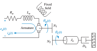
FIGURE P3.11 Motor and load
Expert Solution & Answer
Want to see the full answer?
Check out a sample textbook solution
Students have asked these similar questions
Represent the system shown in Figure P3.7 in state space where the output is 01 (t).
T(1)
N1 = 30
2 N-m/rad 3 N-m-s/rad
TON-m/rad N2= 300
N3 = 10
N4 = 100
OL(t)
-- TTTT
200 N-m-s/rad
FIGURE P3.7
2. Assume a 2 DOF rigid body with a rigid bar, which is supported by a two-spring damper
:3k4, m =
supports. Inertia and length of the rigid body are I
=
10kg and L= 4m.
(a) Derive the mathematical model of the system in variable form
(b) Write the state space representation of the above system.
(c) k₁= k₂ = 800N.m and c₁ = C₂ = 350N.s/m Develop a simulink model and plot all
the system response for input y = sin(wt), where w 1 rad
=
S
(d) k₁ 400v, k₂ 800N.m and c₁ = 175N.s/m, c₂ 350N.s/m Develop a simulink
model and plot all the system response for input y = sin(wt), where w = = 1 rad
8
-
L/4
k₁,c
m, I
L/4
k₂,c
y = sin wt
Represent the translational mechanical system shown
in Figure P3.5 in state space, where x1(t) is the output.
[Section: 3.4]
x2(1)
x3(1)
M3 = 1 kg
fv, = 1 N-s/m
fv,= 1 N-s/m
K1 = 1 N/m
000 M: = 2 kg
+ x1(1)
f() --
K2 = 1 N/m
M1 = 1 kg
fv,= 1 N-s/m
FIGURE P3.5
Chapter 3 Solutions
Control Systems Engineering
Ch. 3 - Prob. 1RQCh. 3 - State an advantage of the transfer function...Ch. 3 - Define state variables.Ch. 3 - Define state.Ch. 3 - Define state vector.Ch. 3 - Define state space.Ch. 3 - What is required to represent a system in state...Ch. 3 - 8. An eighth-order system would be represented in...Ch. 3 - If the state equations are a system of first-order...Ch. 3 - Prob. 10RQ
Ch. 3 - What factors influence the choice of state...Ch. 3 - What is a convenient choice of state variables for...Ch. 3 - If an electrical network has three energy-storage...Ch. 3 - Prob. 14RQCh. 3 - Prob. 1PCh. 3 - Represent the electrical network shown in Figure...Ch. 3 - Prob. 3PCh. 3 - Represent the system shown in Figure P3.4 in state...Ch. 3 - Represent the rotational mechanical system shown...Ch. 3 - Represent the system shown in Figure P3.7 in state...Ch. 3 - 8. Show that the system of Figure 3.7 in the text...Ch. 3 - Find the state-space representation in...Ch. 3 - MATLAB ML 10. Repeat Problem 9 using MATLAB....Ch. 3 - For each system shown in Figure P3.9, write the...Ch. 3 - MATLAB ML
12. Repeat Problem 11 using MATLAB....Ch. 3 - 13. Represent the following transfer function in...Ch. 3 - Find the transfer function G(s) = Y(s)/R(s) for...Ch. 3 - MATLAB ML
15. Use MATLAB to find the transfer...Ch. 3 - 17. A missile in flight, as shown in Figure P3.10,...Ch. 3 - Given the dc servomotor and load shown in Figure...Ch. 3 - Prob. 20PCh. 3 - Prob. 23PCh. 3 - Experiments to identify precision grip dynamics...Ch. 3 - State-space representations are, in general, not...Ch. 3 - Figure P3.16 shows a schematic description of the...Ch. 3 - Prob. 28PCh. 3 - A single-pole oil cylinder valve contains a spool...Ch. 3 - Figure P3.17 shows a free-body diagram of an...Ch. 3 - 33. Parabolic trough collector. A transfer...
Knowledge Booster


Learn more about
Need a deep-dive on the concept behind this application? Look no further. Learn more about this topic, mechanical-engineering and related others by exploring similar questions and additional content below.Similar questions
- The following EOMs describe the behavior of a dynamic system ( à = -K₁a + din b = K₁a - K₂b K₂b - K3c = ċ Assume K₁, K2, K3 are constant, and din is the input. A. How many states does this system of equations have, and why? B. Write the state space form of the system as x = Ax + Bu. You will have to define your state vector and input vector. Clearly identify the matrices. C. Assume the desired output of the system is the vector y that consists of a and K₂b as individual elements. Write the output equation in the form of y = Cx + Du. Clearly identify the matrices.arrow_forward3m ä+4cx+2kx = 4cj+3ky For the system given above, obtain the state-space representation.arrow_forwardConsider the following state space system 1 B = 1 C =[1 0] D=[0] -5 -6 1- Check the controllability of the system. 2- Check the observability of the systemarrow_forward
- For the following state-space representation,define the:– State Vector– System Matrix– Feedforward Matrix– Input Matrix & Input Vector– Output Matrix & Output Vectorarrow_forward3. Consider the system shown below. The outputs of the system are the angular displacement of the upper gear (positive about the x-axis) and the Contact force between the upper and lower gear. Assume that the initial conditions for all state variables are zero and that the gears are massless. There are two inputs Ti(t) acting on the top gear and T₂(t) acting on the rightmost disk. If you let • 9₁ denote the state variable for the spring 92 denote the state variable for the rightmost disk. u₁ denote T₁. u₂ denote T₂. You should expect to get the following state space representation and 9= KR + 0₁ 0 LIR -1. 7/2 Ti(t) Jun 0:0⁰ 40² T₂(t) 03 Figure 3: System for problem 3 21 (a) Derive the state-space model (state equation and output equation) in vector form. (b) For the system parameters I = 8 kg m², k = 1 N m,b=2 N s m/rad, R₁ = 1 m, and R₂ = 3 m: i. Use MATLAB to determine the transfer function matrix [G(s)]. ii. What is the ristic equation AS the system? iii. What are the values of the…arrow_forwardQuestion 3. Consider a mass-spring translational mechanical system in series. The spring has a nonlinear characteristics such that the relationship between the spring force and the spring displacement can be described mathematically f.(t) = 3x. Assume that the applied force is f(t) = 6+ 8f (t), where 8f(t) is a small force about the 6 Newton constant value. Assuming the output to be the displacement of the mass, obtain the state space representation of the system about the equilibrium displacement.arrow_forward
- Consider the translational mechanical system as shown in Figure Q3 with two force inputs, F,(t) and F2(t) being applied on Ma and M3 respectively. Derive the equations of motion for each mass M,, M2 and M3. Then, determine the state space representation of the system if the state variables are as: X(t) = [x, (t) *(e) x2(t) i(t) x3(t) ž()]". The output of the system is taken as displacement at x, (t). X1(t) X3(t) K X2(t) F2(t) M1 M3 M2 F1(t) Figure Q3arrow_forwardRepresent the translational mechanical system shown in state space, where x3(t) is the output.arrow_forward26. For the system shown in Figure P4.8, a step torque is applied at 01 (t). Find a. The transfer function, G(s) = 02(s)/T(s). b. The percent overshoot, settling time, and peak time for 02(t). [Section: 4.6] T(t) 01(1) 02(1) ff 1.07 kg-m2 1.53 N-m-s/rad 1.92 N-m/rad FIGURE P4.8arrow_forward
- 28. Find the transfer function, G(s) = X1(s)/F(s), for the translational mechanical system shown in Figure P2.13. [Section: 2.5] 2 N-s/m X3(1) 2 N-s/m (1)'x- [4 kg 2 N-s/m 6 N/m 6 N/m 4 kg 0000 4 kg "Frictionless FIGURE P2.13 USE MATRIX METHODarrow_forwarda) Determine the state space representation for the translational mechanical system shown in Figure Q4(a), where force, f(t) and displacement, x(t) are the input and output of the system respectively. Use these state variables in your answer. oooo K M -x(1) -ƒ(1)arrow_forward3. In this problem, you are going to analyze the dynamics of a rotational mechanical system shown in Figure below (this is also covered in Lecture Notes #3 of M. Mert Ankarali [1]). In this system input the external torque t(t), and output is the angular velocity of the load wL(t). JR WR OR K JL OL WL T DL DR The state-space representation of this system is provided in the Lecture Notes #3 [1]. Find the transfer function of the dynamical system. Find another (minimal) state-space representation for the system.arrow_forward
arrow_back_ios
SEE MORE QUESTIONS
arrow_forward_ios
Recommended textbooks for you
 Elements Of ElectromagneticsMechanical EngineeringISBN:9780190698614Author:Sadiku, Matthew N. O.Publisher:Oxford University Press
 Mechanics of Materials (10th Edition)Mechanical EngineeringISBN:9780134319650Author:Russell C. HibbelerPublisher:PEARSON
 Thermodynamics: An Engineering ApproachMechanical EngineeringISBN:9781259822674Author:Yunus A. Cengel Dr., Michael A. BolesPublisher:McGraw-Hill Education
 Control Systems EngineeringMechanical EngineeringISBN:9781118170519Author:Norman S. NisePublisher:WILEY
 Mechanics of Materials (MindTap Course List)Mechanical EngineeringISBN:9781337093347Author:Barry J. Goodno, James M. GerePublisher:Cengage Learning
 Engineering Mechanics: StaticsMechanical EngineeringISBN:9781118807330Author:James L. Meriam, L. G. Kraige, J. N. BoltonPublisher:WILEY
Elements Of Electromagnetics
Mechanical Engineering
ISBN:9780190698614
Author:Sadiku, Matthew N. O.
Publisher:Oxford University Press
Mechanics of Materials (10th Edition)
Mechanical Engineering
ISBN:9780134319650
Author:Russell C. Hibbeler
Publisher:PEARSON
Thermodynamics: An Engineering Approach
Mechanical Engineering
ISBN:9781259822674
Author:Yunus A. Cengel Dr., Michael A. Boles
Publisher:McGraw-Hill Education
Control Systems Engineering
Mechanical Engineering
ISBN:9781118170519
Author:Norman S. Nise
Publisher:WILEY
Mechanics of Materials (MindTap Course List)
Mechanical Engineering
ISBN:9781337093347
Author:Barry J. Goodno, James M. Gere
Publisher:Cengage Learning
Engineering Mechanics: Statics
Mechanical Engineering
ISBN:9781118807330
Author:James L. Meriam, L. G. Kraige, J. N. Bolton
Publisher:WILEY
Ch 2 - 2.2.2 Forced Undamped Oscillation; Author: Benjamin Drew;https://www.youtube.com/watch?v=6Tb7Rx-bCWE;License: Standard youtube license