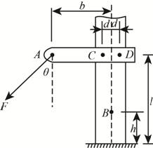
The force F is applied at the end of arm ACD, which is mounted to a vertical post. Replace this single force F by an equivalent force-couple system at B. Next, redistribute this force and couple by replacing it with two forces acting in the same direction as F, one at C and the other at D, and determine the forces supported by the two hex-bolts. Use values of

Trending nowThis is a popular solution!

Chapter 2 Solutions
Engineering Mechanics: Statics
Additional Engineering Textbook Solutions
INTERNATIONAL EDITION---Engineering Mechanics: Statics, 14th edition (SI unit)
Degarmo's Materials And Processes In Manufacturing
Java: An Introduction to Problem Solving and Programming (8th Edition)
Starting Out with C++ from Control Structures to Objects (9th Edition)
Web Development and Design Foundations with HTML5 (8th Edition)
Starting Out with Programming Logic and Design (5th Edition) (What's New in Computer Science)
- Q2] (20 Marks) A steam turbine with one open feed water heater (OFWH) as shown in the following figure. In terms of enthalpies and y determine: 1- Work of HPT 2- Work of LPT 3- Work at Pump1 4- Work at Pump2 5-The heat added at the boiler 6- The quantity (y) in terms of enthalpies 7-Heat extracted from condenser 5 Boiler 2岁 3 OFWH 9 Pump2 HPT LPT 8 Pump1 O Condenserarrow_forward11.2 Boxes A and B are at rest on a conveyer belt that is initially at rest. The belt suddenly starts in an upward direction so that slipping instantly occurs between the belt and the boxes. The kinetic friction coefficients between the belt and the boxes are μk,A = 0.3 and μk,B = 0.32. Determine the initial acceleration of each box. Will the blocks stay together, or separate? 80 lb 100 lb A B 15° Hint: to see if the boxes stay together or separate, first assume they separate, and see if their resulting motion (acceleration) validates that assumption. If the their motion is not consistent with the assumption of separation, then they must stay together.arrow_forwardAn ideal gas is enclosed in a cylinder which has a movable piston. The gas is heated, resulting in an increase in temperature of the gas, and work is done by the gas on the piston so that the pressure remains constant. a) Is the work done by the gas negative, positive or zero? b) From a microscopic view, how is the internal energy of the gas molecules affected? c) Is the heat less than, greater than or equal to the work? Explain you answer.arrow_forward
- I need to adapt a real-life system to this assignment. It doesn't need to be a very complicated system. I am a senior mechanical engineering student. I need help with my mechanical theory homeworkarrow_forwardstate all the formulae associated with adiabatic processarrow_forwardDesign a Moore type synchronous state machine with three external inputs A1, A2, A3 and one output signal F. The output F goes to 1 when A1.A2.-A3 = 1 at the next system timing event. The output F stays at 1 as long as A3=0; otherwise, the output goes to 0. (Note: use a positive edge-triggered D flip-flop in the design) Write a VHDL code to describe the implementation of one-digit decimal counter using PROCESS.arrow_forward
- State all the formulae associated with the Isothermal Process.arrow_forward: +0 العنوان solle не Am 4 A pump draws water through a 300-mm diameter cast iron pipe, 15m long from a reservoir in which the water surface is 4.5 m higher than the pump and discharges through a 250- mm diameter cast iron, 75 m long, to an elevated tank in which the water surface is 60 m higher than the pump. Q=0.25 m³/s. Considering f-0.02 and the coefficients for minor head losses (k entrance 0.5, k bend 0.35, and K exit -0.5), compute the power of the pump. ۳/۱ ۲/۱ 4.5 m Kentrance 300 mm dia. 15 m Length 250 mm dia. 75 m Length kpend kexit 60 m ostlararrow_forwardA 100 m length of a smooth horizontal pipe is attached to a large reservoir. A attached to the end of the pipe to pump water into the reservoir at a volume flow rate of 0.01 m³/s. What pressure (gage) must the pump produce at the pipe to generate this flow rate? The inside diameter of the smooth pipe is 150mm. Dynamic Viscosity of water is 1*103 Kg/(m.s). K at the exit of the pipe is 1. pump 10 m D=150mm L= 100 m- Pumparrow_forward
- : +0 العنوان solle не A 4 A numn drawe water through 200 ۳/۱ ۲/۱ A heavy car plunges into a lake during an accident and lands at the bottom of the lake on its wheels as shown in figure. The door is 1.2 m high and 1 m wide, and the top edge of the door is 8 m below the free surface of the water. Determine the hydrostatic force on the door if it is located at the center of the door, and discuss if the driver can open the door, if not; suggest a way for him to open it. Assume a strong person can lift 100 kg, the passenger cabin is well-sealed so that no water leaks inside. The door can be approximated as a vertical rectangular plate. 8 m E ✓ Lakearrow_forwardTwo concentric plain helical springs of the same length are wound out of the samewire circular in cross section and supports a compressive load P. The inner springmean diameter 200 mm. Calculate the maximum stress induced in the spring if theconsists of 20 turns of mean dimeter 160 mm and the outer spring has 18 turns ofdiameter of wire is equal to 10 mm and Pis equal to 1000 N. (Take Ks=1)arrow_forwardt 1+2\xi pu +962гz P 1 A heavy car plunges into a lake during an accident and lands at the bottom of the lake on its wheels as shown in figure. The door is 1.2 m high and I m wide, and the top edge of the door is 8 m below the free surface of the water. Determine the hydrostatic force on the door if it is located at the center of the door, and discuss if the driver can open the door, if not; suggest a way for him to open it. Assume a strong person can lift 100 kg, the passenger cabin is well-sealed so that no water leaks inside. The door can be approximated as a vertical rectangular plate. 加 8 m 1.2 m Lake -20125 DI 750 x2.01 5 P 165 Xarrow_forward
 Elements Of ElectromagneticsMechanical EngineeringISBN:9780190698614Author:Sadiku, Matthew N. O.Publisher:Oxford University Press
 Mechanics of Materials (10th Edition)Mechanical EngineeringISBN:9780134319650Author:Russell C. HibbelerPublisher:PEARSON
 Thermodynamics: An Engineering ApproachMechanical EngineeringISBN:9781259822674Author:Yunus A. Cengel Dr., Michael A. BolesPublisher:McGraw-Hill Education
 Control Systems EngineeringMechanical EngineeringISBN:9781118170519Author:Norman S. NisePublisher:WILEY
 Mechanics of Materials (MindTap Course List)Mechanical EngineeringISBN:9781337093347Author:Barry J. Goodno, James M. GerePublisher:Cengage Learning
 Engineering Mechanics: StaticsMechanical EngineeringISBN:9781118807330Author:James L. Meriam, L. G. Kraige, J. N. BoltonPublisher:WILEY


