Concept explainers
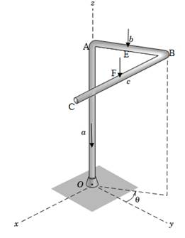
The body is composed of a slender uniform rod bent into the shape shown and having a mass

Want to see the full answer?
Check out a sample textbook solution
Chapter 2 Solutions
Engineering Mechanics: Statics
Additional Engineering Textbook Solutions
Starting Out with Java: From Control Structures through Objects (7th Edition) (What's New in Computer Science)
HEAT+MASS TRANSFER:FUND.+APPL.
Web Development and Design Foundations with HTML5 (8th Edition)
Computer Science: An Overview (13th Edition) (What's New in Computer Science)
Database Concepts (8th Edition)
Starting Out With Visual Basic (8th Edition)
- : +0 العنوان solle не Am 4 A pump draws water through a 300-mm diameter cast iron pipe, 15m long from a reservoir in which the water surface is 4.5 m higher than the pump and discharges through a 250- mm diameter cast iron, 75 m long, to an elevated tank in which the water surface is 60 m higher than the pump. Q=0.25 m³/s. Considering f-0.02 and the coefficients for minor head losses (k entrance 0.5, k bend 0.35, and K exit -0.5), compute the power of the pump. ۳/۱ ۲/۱ 4.5 m Kentrance 300 mm dia. 15 m Length 250 mm dia. 75 m Length kpend kexit 60 m ostlararrow_forwardA 100 m length of a smooth horizontal pipe is attached to a large reservoir. A attached to the end of the pipe to pump water into the reservoir at a volume flow rate of 0.01 m³/s. What pressure (gage) must the pump produce at the pipe to generate this flow rate? The inside diameter of the smooth pipe is 150mm. Dynamic Viscosity of water is 1*103 Kg/(m.s). K at the exit of the pipe is 1. pump 10 m D=150mm L= 100 m- Pumparrow_forward: +0 العنوان solle не A 4 A numn drawe water through 200 ۳/۱ ۲/۱ A heavy car plunges into a lake during an accident and lands at the bottom of the lake on its wheels as shown in figure. The door is 1.2 m high and 1 m wide, and the top edge of the door is 8 m below the free surface of the water. Determine the hydrostatic force on the door if it is located at the center of the door, and discuss if the driver can open the door, if not; suggest a way for him to open it. Assume a strong person can lift 100 kg, the passenger cabin is well-sealed so that no water leaks inside. The door can be approximated as a vertical rectangular plate. 8 m E ✓ Lakearrow_forward
- Two concentric plain helical springs of the same length are wound out of the samewire circular in cross section and supports a compressive load P. The inner springmean diameter 200 mm. Calculate the maximum stress induced in the spring if theconsists of 20 turns of mean dimeter 160 mm and the outer spring has 18 turns ofdiameter of wire is equal to 10 mm and Pis equal to 1000 N. (Take Ks=1)arrow_forwardt 1+2\xi pu +962гz P 1 A heavy car plunges into a lake during an accident and lands at the bottom of the lake on its wheels as shown in figure. The door is 1.2 m high and I m wide, and the top edge of the door is 8 m below the free surface of the water. Determine the hydrostatic force on the door if it is located at the center of the door, and discuss if the driver can open the door, if not; suggest a way for him to open it. Assume a strong person can lift 100 kg, the passenger cabin is well-sealed so that no water leaks inside. The door can be approximated as a vertical rectangular plate. 加 8 m 1.2 m Lake -20125 DI 750 x2.01 5 P 165 Xarrow_forward11. If Sin(x+α) = 2Cos(x-a); prove that: tan x= 2- tana 1-2 tanaarrow_forward
- 12. If Sin(x-a)= Cos(x+α); prove that: tan x=1.arrow_forward: +0 العنوان solle не A 4 A numn drawe water through 200 ۳/۱ ۲/۱ A heavy car plunges into a lake during an accident and lands at the bottom of the lake on its wheels as shown in figure. The door is 1.2 m high and 1 m wide, and the top edge of the door is 8 m below the free surface of the water. Determine the hydrostatic force on the door if it is located at the center of the door, and discuss if the driver can open the door, if not; suggest a way for him to open it. Assume a strong person can lift 100 kg, the passenger cabin is well-sealed so that no water leaks inside. The door can be approximated as a vertical rectangular plate. 8 m E ✓ Lakearrow_forward۲/۱ - | العنوان A heavy car plunges into a lake during an accident and lands at the bottom of the lake on its wheels as shown in figure. The door 1.2 m high and 1 m wide, and the top edge of the door is 8 m below the free surface of the water. Determine the hydrostatic force on the door if it is located at the center of the door, and discuss if the driver can open the door, if not; suggest a way for him to open it. Assume a strong person can lift 100 kg, the passenger cabin is well-sealed so that no water leaks inside. The door can be approximated as a vertical rectangular plate. 8 m Lakearrow_forward
- - | A pump draws water through a 300-mm diameter cast iron pipe, 15m long from a reservoir in which the water surface is 4.5 m higher than the pump and discharges through a 250- mm diameter cast iron, 75 m long, to an elevated tank in which the water surface is 60 m higher than the pump. Q-0.25 m³/s. Considering f- 0.02 and the coefficients for minor head losses (k entrance 0.5, k bend 0.35, and K exit -0.5), compute the power of the pump. Kexit 250 mm dia 75 m Length 60 m العنوان 300 mm dia. 15 m Length -UZ kentrance 11421 Kpend osthor oster ۲/۱arrow_forwardA heavy car plunges into a lake during an accident and lands at the bottom of the lake on its wheels as shown in figure. The door is 1.2 m high and 1 m wide, and the top edge of the door is 8 m below the free surface of the water. Determine the hydrostatic force on the door if it is located at the center of the door, and discuss if the driver can open the door, if not; suggest a way for him to open it. Assume a strong person can lift 100 kg, the passenger cabin is well-sealed so that no water leaks inside. The door can be approximated as a vertical rectangular plate. 8 m m Lakearrow_forward۲/۱ A pump draws water through a 300-mm diameter cast iron pipe, 15m long from a reservoir in which the water surface is 4.5 m higher than the pump and discharges through a 250- mm diameter cast iron, 75 m long, to an elevated tank in which the water surface is 60 m higher than the pump. Q = 0.25 m³/s. Considering f= 0.02 and the coefficients for minor head losses (k entrance = 0.5, k hend 0.35, and K exit -0.5), compute the power of the pump. 4.5 m 300 mm dia. 15 m Length 250 mm dia. 75 m Length kentrance kexit 60 m kbend ostherarrow_forward
 Elements Of ElectromagneticsMechanical EngineeringISBN:9780190698614Author:Sadiku, Matthew N. O.Publisher:Oxford University Press
 Mechanics of Materials (10th Edition)Mechanical EngineeringISBN:9780134319650Author:Russell C. HibbelerPublisher:PEARSON
 Thermodynamics: An Engineering ApproachMechanical EngineeringISBN:9781259822674Author:Yunus A. Cengel Dr., Michael A. BolesPublisher:McGraw-Hill Education
 Control Systems EngineeringMechanical EngineeringISBN:9781118170519Author:Norman S. NisePublisher:WILEY
 Mechanics of Materials (MindTap Course List)Mechanical EngineeringISBN:9781337093347Author:Barry J. Goodno, James M. GerePublisher:Cengage Learning
 Engineering Mechanics: StaticsMechanical EngineeringISBN:9781118807330Author:James L. Meriam, L. G. Kraige, J. N. BoltonPublisher:WILEY


