
Concept explainers
Videos
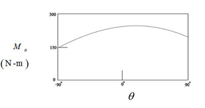
A flagpole with attached light triangular frame is shown here for an arbitrary position during its raising. The 75-N tension in the erecting cable remains constant. Determine and plot the moment about the pivot O of the 75-N force for the range 0≤θ≤90°. Determine the maximum value of this moment and the elevation angle at which it occurs; comment on the physical significance of the latter. The effects of the diameter of the drum at D may be neglected.
Want to see the full answer?
Check out a sample textbook solution
Chapter 2 Solutions
Engineering Mechanics: Statics
Additional Engineering Textbook Solutions
Mechanics of Materials (10th Edition)
Java How to Program, Early Objects (11th Edition) (Deitel: How to Program)
Starting Out with Java: From Control Structures through Objects (7th Edition) (What's New in Computer Science)
Starting Out with C++ from Control Structures to Objects (9th Edition)
Elementary Surveying: An Introduction To Geomatics (15th Edition)
Management Information Systems: Managing The Digital Firm (16th Edition)


- 0,5 mm 450 mm 350 mm Bronze A = 1500 mm² E = 105 GPa प 21.6 × 10-PC Aluminum A = 1800 mm² £ = 73 GPa = a 23.2 × 10-PC PROBLEM 2.58 Knowing that a 0.5-mm gap exists when the temperature is 24°C, determine (a) the temperature at which the normal stress in the aluminum bar will be equal to -75 MPa, (b) the corresponding exact length of the aluminum bar.arrow_forward0.5 mm 450 mm -350 mm Bronze Aluminum A 1500 mm² A 1800 mm² E 105 GPa E 73 GPa K = 21.6 X 10 G < = 23.2 × 10-G PROBLEM 2.59 Determine (a) the compressive force in the bars shown after a temperature rise of 82°C, (b) the corresponding change in length of the bronze bar.arrow_forwardThe truss shown below sits on a roller at A and a pin at E. Determine the magnitudes of the forces in truss members GH, GB, BC and GC. State whether they are in tension or compression or are zero force members.arrow_forward
- A weight (W) hangs from a pulley at B that is part of a support frame. Calculate the maximum possible mass of the weight if the maximum permissible moment reaction at the fixed support is 100 Nm. Note that a frictionless pin in a slot is located at C.arrow_forwardIt is the middle of a winter snowstorm. Sally and Jin take shelter under an overhang. The loading of the snow on top of the overhang is shown in the figure below. The overhang is attached to the wall at points A and B with pin supports. Another pin is at C. Determine the reactions of the pin supports at A and B. Express them in Cartesian vector form.arrow_forwardRecall that the CWH equation involves two important assumptions. Let us investigate how these assumptions affect the accuracy of state trajectories under the control inputs optimized in (a) and (b). (c.1): Discuss the assumptions about the chief and deputy orbits that are necessary for deriving CWH.arrow_forward
- PROBLEM 2.50 1.8 m The concrete post (E-25 GPa and a = 9.9 x 10°/°C) is reinforced with six steel bars, each of 22-mm diameter (E, = 200 GPa and a, = 11.7 x 10°/°C). Determine the normal stresses induced in the steel and in the concrete by a temperature rise of 35°C. 6c " 0.391 MPa 240 mm 240 mm 6₁ = -9.47 MPaarrow_forwardFor some viscoelastic polymers that are subjected to stress relaxation tests, the stress decays with time according to a(t) = a(0) exp(-4) (15.10) where σ(t) and o(0) represent the time-dependent and initial (i.e., time = 0) stresses, respectively, and t and T denote elapsed time and the relaxation time, respectively; T is a time-independent constant characteristic of the material. A specimen of a viscoelastic polymer whose stress relaxation obeys Equation 15.10 was suddenly pulled in tension to a measured strain of 0.5; the stress necessary to maintain this constant strain was measured as a function of time. Determine E (10) for this material if the initial stress level was 3.5 MPa (500 psi), which dropped to 0.5 MPa (70 psi) after 30 s.arrow_forwardFor the flows in Examples 11.1 and 11.2, calculate the magnitudes of the Δ V2 / 2 terms omitted in B.E., and compare these with the magnitude of the ℱ terms.arrow_forward
- Calculate ℛP.M. in Example 11.2.arrow_forwardQuestion 22: The superheated steam powers a steam turbine for the production of electrical power. The steam expands in the turbine and at an intermediate expansion pressure (0.1 MPa) a fraction is extracted for a regeneration process in a surface regenerator. The turbine has an efficiency of 90%. It is requested: Define the Power Plant Schematic Analyze the steam power system considering the steam generator system in the attached figure Determine the electrical power generated and the thermal efficiency of the plant Perform an analysis on the power generated and thermal efficiency considering a variation in the steam fractions removed for regeneration ##Data: The steam generator uses biomass from coconut shells to produce 4.5 tons/h of superheated steam; The feedwater returns to the condenser at a temperature of 45°C (point A); Monitoring of the operating conditions in the steam generator indicates that the products of combustion leave the system (point B) at a temperature of 500°C;…arrow_forwardThis is an old practice exam question.arrow_forward
 International Edition---engineering Mechanics: St...Mechanical EngineeringISBN:9781305501607Author:Andrew Pytel And Jaan KiusalaasPublisher:CENGAGE L