
Videos
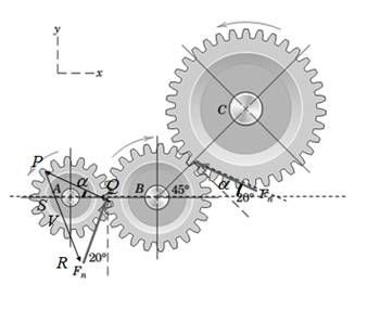
Power is to be transferred from the pinion A to the output gear C inside a
N, and these forces are shown acting on idler gear B. Determine the magnitude of the resultant R of the two contact forces acting on the idler gear. Complete both a graphical and a
Want to see the full answer?
Check out a sample textbook solution
Chapter 2 Solutions
Engineering Mechanics: Statics
Additional Engineering Textbook Solutions
Mechanics of Materials
Manufacturing Engineering & Technology
Applied Statics and Strength of Materials (6th Edition)
Degarmo's Materials And Processes In Manufacturing
Engineering Mechanics: Statics
Engineering Mechanics: Dynamics (14th Edition)


- Given the Position vector Ř = -i+ 6j+ 3k (m) and the Force vector F = -i – 3j + 8k (kN) Determine R. F Answer:arrow_forwardwith the following modifications: Replace the vertical 6kN at point B with a horizontal force 6kN acting to the right at the same point.arrow_forwardDetermine resultent of the following system of forces.arrow_forward
- On the structure shown act the force of 180.0 N and the torque formed by the forces P and Q. If P = Q = 45.0 N; replace this system by a resultant force R equivalent.(a) Find the magnitude and direction of the resulting R.(b) Specify the point where the line of action of force resultant intersects the z-axis.arrow_forwardArticle 2/8 Problems 81 2/119 The figure of Prob. 2/101 is ahown agin here. Ir the magnitude of the moment of F about line CD is 50 N-m, dotormine the magnitudo of F. 2/121 A 50-lb forse is applied to the control pedal as nhown. The force lies in a plane parallel to the re plane and is perpendieular to BC. Determine the mnments of this foren about point O and about the shaft GA. Ane F- 998 N Ans. M -90. - 09oj - 20sk Ib-in. Maa-690 Ib-in. 02 m 0.2 m A 0.2 m 04 m Problem 2/119 Representative Problems 2/120 Two 1.2-lb thrusters on the nonrotating satellite are aimultaneously firod an ehown. Compute the mo- ment aciated with this couple and state about which wtellite axes rotations will begin to accur. 50 lb Problem 2/121 2/122 A moment (torque M applied to the shat and at- tached arm causes a tension T of 120 lb applied to A by the restraining enble AB. Determine the mo- ment M, of the tension about point 0. 1.3 Ih 20 14" 60 1.2 Ib M T-120 lb 16 Problem 2/120 Problem 2/122arrow_forwardGiven the Position vector R= 2i -j+ 3k (m) and the Force vector F = i+j+k (kN) Determine the angle in degrees between the two vectors. Answer:arrow_forward
- Q4b. Force vectors F1 and F2 act on body Pwith the resultant force vector R. The resultant force R= 575 N and the angle between Rand the x-axis is of 320. If F1 = 275 N and the angle between F1 and the x-axis is 560, determine the angle between F2 and the x-axis. *Assume coplanar vector forces and give your answer in degrees to two decimal places. Body, P Answer: y F1 R F2arrow_forwardThe example device shown is part of the seatback release mechanism. The part is subjected to a N-4 force exerted at A and a recovery moment of 300 - N • mm exerted by a hidden torsional spring. Determine y - the intersection of the line of action of the only equivalent force.arrow_forwardthe three showed forces are equivalent to one ascending force of 50kN in A and has a torque of 170kN*m in couter-clockwise sense. Determine P and Qarrow_forward
- 2 - The 200-N force produces a torque (moment) of 40 N.m about the axis of the bolt in order to tighten the hexagonal nut . Find the forces between the smooth jaws of the wrench and the 20 mm 200 N nut if contact occurs at the corners A and B of the hexagon.arrow_forwardGiven the Position vector Ř = i+j+3k (m) and the Force vector F = i - 7j + 2k (kN Determine the angle in degrees between the two vectors. Answer:arrow_forwardF- 10N 250 mm The 10-N force is applied to the handle of the hy- draulic control valve as shown. Calculate the mo- 60 17.5 mm ment of this force about point O.arrow_forward
 International Edition---engineering Mechanics: St...Mechanical EngineeringISBN:9781305501607Author:Andrew Pytel And Jaan KiusalaasPublisher:CENGAGE L