
Electronics Fundamentals: Circuits, Devices & Applications
8th Edition
ISBN: 9780135072950
Author: Thomas L. Floyd, David Buchla
Publisher: Prentice Hall
expand_more
expand_more
format_list_bulleted
Concept explainers
Videos
Textbook Question
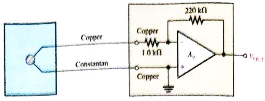
Chapter 21, Problem 3P
Determine the output voltage of the op-amp in Figure 21-45 if the thermocouple is measuring a temperature of
Refer to Table 21-1.
Expert Solution & Answer
Want to see the full answer?
Check out a sample textbook solution
Students have asked these similar questions
please work out the following using the infomation in the attached photo. This is for a Boost converter
(a) Output voltage(b) Inductor current ripple (assume it is 20%)
(c) Switching frequency (d) Output current
(e) Output voltage ripple
You are required to apply a DC bridge to control the temperature of a heaterusing a thermistor, an amplifier, a transistor, and some basic electroniccomponents. Sketch the schematic diagram with labels.
1.EXPLAIN THE CHARACTERISTICS OF AN OPAMP?
2.WHAT ARE THE CHANGES IN THE AMPLIFICATION DURING LOW FREQUENCY
Chapter 21 Solutions
Electronics Fundamentals: Circuits, Devices & Applications
Ch. 21 - A thermocouple can measure higher temperatures...Ch. 21 - Thermocouples are commonly used to measure body...Ch. 21 - An advantage of an RTD over a thermistor is that...Ch. 21 - Prob. 4TFQCh. 21 - A thermocouple signal conditioner must have high...Ch. 21 - Signal conditioning for temperature sensors...Ch. 21 - Prob. 7TFQCh. 21 - Absolute pressure is measured relative to the...Ch. 21 - In a sample-and-hold circuit, an analog value is...Ch. 21 - Prob. 10TFQ
Ch. 21 - A thermocouple a change in resistance for a change...Ch. 21 - In a thermocouple circuit, where each of the...Ch. 21 - A thermocouple signal conditioner is designed to...Ch. 21 - Prob. 4STCh. 21 - Prob. 5STCh. 21 - Prob. 6STCh. 21 - Prob. 7STCh. 21 - Prob. 8STCh. 21 - Prob. 9STCh. 21 - Prob. 10STCh. 21 - Prob. 11STCh. 21 - Prob. 12STCh. 21 - Prob. 13STCh. 21 - Prob. 14STCh. 21 - In an analog switch, the aperture time is the time...Ch. 21 - Prob. 16STCh. 21 - An analog signal must be sampled at a minimum rate...Ch. 21 - Prob. 18STCh. 21 - Prob. 19STCh. 21 - Prob. 20STCh. 21 - Prob. 21STCh. 21 - Three identical thermocouples are each exposed to...Ch. 21 - You have two thermocouples. One is a K type and...Ch. 21 - Determine the output voltage of the op-amp in...Ch. 21 - What should be the output voltage in Problem 3 if...Ch. 21 - Prob. 5PCh. 21 - Prob. 6PCh. 21 - Explain the difference in the results of Problems...Ch. 21 - Prob. 8PCh. 21 - A certain material being measured undergoes a...Ch. 21 - Explain how a strain gauge can be used to measure...Ch. 21 - Identify and compare the three symbols in Figure...Ch. 21 - Determine the output voltage waveform for the...Ch. 21 - Repeat Problem 12 for the waveforms in Figure...Ch. 21 - Name two ways an SCR can be placed in the...Ch. 21 - Sketch the VR waveform for the circuit in Figure...Ch. 21 - For the circuit in Figure 21-53, describe the...Ch. 21 - What change to the circuit in Figure 21-53 would...
Knowledge Booster


Learn more about
Need a deep-dive on the concept behind this application? Look no further. Learn more about this topic, electrical-engineering and related others by exploring similar questions and additional content below.Similar questions
- Q.No.4: A flash type analog to digital converter as shown in figure (b). The input is Vin = 5V. Find the digital output. 10 4.0 VDC Vin 1 k2- X2 Bị (MSB) 2k2 Decoder X1 Chip Bo (LSB) 2 k2- Xo 1 k2 Figure (a) Analog to Digital Converterarrow_forward13. The signal conditioning used for a thermocouple is (a) a Wheatstone bridge (b) a differential op-amp circuitarrow_forwardDesign a Buck Converter with the Following Features. Input Voltage = 50 V Output Voltage = 20 V Switching Frequency=6 KHz Output Power = 300 W Efficiency =%85 Current fluctuationı <%10*Input current Output Voltage Ripple<%1*Output Voltagearrow_forward
- A good op-amp has a very high slew rate very low slew rate very high output resistance very low BWarrow_forwardThe input of a voltage follower has a square waveform. Draw the output waveforms (vo) of a voltagefollower for the following 4 input waveforms (vin). The slew rate of the op-amp is 0.25 ఓ௦arrow_forward11. Identify each of the op-amp configurations in Figure 12-63 in www111 + (c)arrow_forward
- For opamp which has input voltages Vi1 = 160 µV Vi2= 50 µV Differential gain Ad= 80 CMRR= 1.00e3 Please calculate the output voltage. Please give the answer in µV, do not include anything else than the answer and the format will be 0.01e+6 or 1.02e-4.arrow_forwardDescribe the changes in the output voltage with respect to the input. Insert a multisim screenshot of Vin and Vout. Label completely. Identify what type of clamper circuit is being simulated.arrow_forward3Z The most usual form of op-amp package a.type TO-5 metal cans b.integration packages c.dual in-line packages d.type TO-8 metal cansarrow_forward
arrow_back_ios
SEE MORE QUESTIONS
arrow_forward_ios
Recommended textbooks for you
 Introductory Circuit Analysis (13th Edition)Electrical EngineeringISBN:9780133923605Author:Robert L. BoylestadPublisher:PEARSON
 Delmar's Standard Textbook Of ElectricityElectrical EngineeringISBN:9781337900348Author:Stephen L. HermanPublisher:Cengage Learning
 Programmable Logic ControllersElectrical EngineeringISBN:9780073373843Author:Frank D. PetruzellaPublisher:McGraw-Hill Education
 Fundamentals of Electric CircuitsElectrical EngineeringISBN:9780078028229Author:Charles K Alexander, Matthew SadikuPublisher:McGraw-Hill Education
 Electric Circuits. (11th Edition)Electrical EngineeringISBN:9780134746968Author:James W. Nilsson, Susan RiedelPublisher:PEARSON
 Engineering ElectromagneticsElectrical EngineeringISBN:9780078028151Author:Hayt, William H. (william Hart), Jr, BUCK, John A.Publisher:Mcgraw-hill Education,
Introductory Circuit Analysis (13th Edition)
Electrical Engineering
ISBN:9780133923605
Author:Robert L. Boylestad
Publisher:PEARSON
Delmar's Standard Textbook Of Electricity
Electrical Engineering
ISBN:9781337900348
Author:Stephen L. Herman
Publisher:Cengage Learning
Programmable Logic Controllers
Electrical Engineering
ISBN:9780073373843
Author:Frank D. Petruzella
Publisher:McGraw-Hill Education
Fundamentals of Electric Circuits
Electrical Engineering
ISBN:9780078028229
Author:Charles K Alexander, Matthew Sadiku
Publisher:McGraw-Hill Education
Electric Circuits. (11th Edition)
Electrical Engineering
ISBN:9780134746968
Author:James W. Nilsson, Susan Riedel
Publisher:PEARSON
Engineering Electromagnetics
Electrical Engineering
ISBN:9780078028151
Author:Hayt, William H. (william Hart), Jr, BUCK, John A.
Publisher:Mcgraw-hill Education,
Electrical Engineering: Ch 5: Operational Amp (2 of 28) Inverting Amplifier-Basic Operation; Author: Michel van Biezen;https://www.youtube.com/watch?v=x2xxOKOTwM4;License: Standard YouTube License, CC-BY