
Electronics Fundamentals: Circuits, Devices & Applications
8th Edition
ISBN: 9780135072950
Author: Thomas L. Floyd, David Buchla
Publisher: Prentice Hall
expand_more
expand_more
format_list_bulleted
Videos
Textbook Question
Chapter 21, Problem 17P
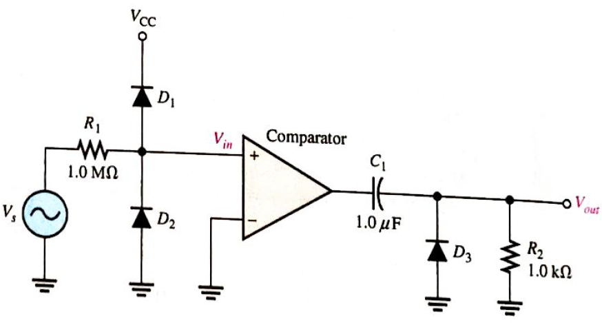
What change to the circuit in Figure 21-53 would you make if you wanted to have positive triggers on the negative slope of the input waveform?
Expert Solution & Answer
Want to see the full answer?
Check out a sample textbook solution
Students have asked these similar questions
For the given circuit, what is the minimum peak value of the output waveform if the input waveform is 10V square wave
with switching time of 1 second? Assume that the input switches between +10V and -10V DC levels.
O V
-5 V
-10 V
-20 V
A filtered rectifier has a 15 Vdc output with 100 mVp-p of ripple. The peak output voltage for the circuit is
A. 47.2 V peak
B. 15.1 Vpeak
C. 14.9 Vpeak
D. 15.05 Vpeak
Class C commutation technique is
forced commutation technique O
complementary commutation
technique
voltage commutation technique O
All of them O
In class C commutation technique
to turn off the SCR T1
gate pulse is given to SCR T1 O
gate pulse is given to SCR T2
collector pulse is given to SCR T1
collector pulse is given to SCR T2 O
Chapter 21 Solutions
Electronics Fundamentals: Circuits, Devices & Applications
Ch. 21 - A thermocouple can measure higher temperatures...Ch. 21 - Thermocouples are commonly used to measure body...Ch. 21 - An advantage of an RTD over a thermistor is that...Ch. 21 - Prob. 4TFQCh. 21 - A thermocouple signal conditioner must have high...Ch. 21 - Signal conditioning for temperature sensors...Ch. 21 - Prob. 7TFQCh. 21 - Absolute pressure is measured relative to the...Ch. 21 - In a sample-and-hold circuit, an analog value is...Ch. 21 - Prob. 10TFQ
Ch. 21 - A thermocouple a change in resistance for a change...Ch. 21 - In a thermocouple circuit, where each of the...Ch. 21 - A thermocouple signal conditioner is designed to...Ch. 21 - Prob. 4STCh. 21 - Prob. 5STCh. 21 - Prob. 6STCh. 21 - Prob. 7STCh. 21 - Prob. 8STCh. 21 - Prob. 9STCh. 21 - Prob. 10STCh. 21 - Prob. 11STCh. 21 - Prob. 12STCh. 21 - Prob. 13STCh. 21 - Prob. 14STCh. 21 - In an analog switch, the aperture time is the time...Ch. 21 - Prob. 16STCh. 21 - An analog signal must be sampled at a minimum rate...Ch. 21 - Prob. 18STCh. 21 - Prob. 19STCh. 21 - Prob. 20STCh. 21 - Prob. 21STCh. 21 - Three identical thermocouples are each exposed to...Ch. 21 - You have two thermocouples. One is a K type and...Ch. 21 - Determine the output voltage of the op-amp in...Ch. 21 - What should be the output voltage in Problem 3 if...Ch. 21 - Prob. 5PCh. 21 - Prob. 6PCh. 21 - Explain the difference in the results of Problems...Ch. 21 - Prob. 8PCh. 21 - A certain material being measured undergoes a...Ch. 21 - Explain how a strain gauge can be used to measure...Ch. 21 - Identify and compare the three symbols in Figure...Ch. 21 - Determine the output voltage waveform for the...Ch. 21 - Repeat Problem 12 for the waveforms in Figure...Ch. 21 - Name two ways an SCR can be placed in the...Ch. 21 - Sketch the VR waveform for the circuit in Figure...Ch. 21 - For the circuit in Figure 21-53, describe the...Ch. 21 - What change to the circuit in Figure 21-53 would...
Knowledge Booster


Learn more about
Need a deep-dive on the concept behind this application? Look no further. Learn more about this topic, electrical-engineering and related others by exploring similar questions and additional content below.Similar questions
- Calculate the dc and ac components of the output signal across load RL in the circuit of Figure * Vác = 150 V V, (ms) = 15 V V', (ms) R 500 2 C2 10μF Full-wave 15 μF 5 k2 rectifier Vdc= 136.4V, Vac= 3.9V Vdc= 163.4V, Vac= 9.3V Vdc= 13.4V, Vac= 9.9V None of the abovearrow_forward20Vp Vout 9V 15V Draw output wave for this circuit mentioning maximum and minimum peak voltagesarrow_forwardin a given figure, a signal is shown on a CRO screen. The CRO voltage per division (Volt/Div.) knob is set on 5 V, and Time per Division (Time/Div) knob is set on 10 ms. Calculate the signal amplitude and frequency. THEICN Ground LEVE NTENS TRO NP FOCUS VO ON INVERT NVERT CHI 40arrow_forward
- For the given circuit, what is the minimum peak value of the output waveform if the input waveform is 10V square wave with switching time of 1 second? Assume that the input switches between +10V and -10V DC levels. O ov O -5V O - 20V O -10Varrow_forwarddesign a triangular wave oscillator with oscillation frequency of (50 KHz) andtriangle wave has Vp-p = 6v with Vcc= 18v draw circuit and output waves (vo1 andVo2)arrow_forwardFind value of K so that the system has: Percent Overshoot less than or equal to 22% 0 to 100 Rise Time less than or equal to 1 ms Peak Time less than or equal to 15 msarrow_forward
- Whats is the effect of Output C filter on the operation of a single-phase bridge rectifierarrow_forwardFor continuous current operation show that the mean value of the DC output Vo = 0.90Vs Cos delay angle in full wave rectifiers single phasearrow_forwardWhat is the noise figure when the input signal and the noise values are 200 and 20uW and the output signal and noise values are 2 and 0.8 W?arrow_forward
arrow_back_ios
SEE MORE QUESTIONS
arrow_forward_ios
Recommended textbooks for you
 Introductory Circuit Analysis (13th Edition)Electrical EngineeringISBN:9780133923605Author:Robert L. BoylestadPublisher:PEARSON
 Delmar's Standard Textbook Of ElectricityElectrical EngineeringISBN:9781337900348Author:Stephen L. HermanPublisher:Cengage Learning
 Programmable Logic ControllersElectrical EngineeringISBN:9780073373843Author:Frank D. PetruzellaPublisher:McGraw-Hill Education
 Fundamentals of Electric CircuitsElectrical EngineeringISBN:9780078028229Author:Charles K Alexander, Matthew SadikuPublisher:McGraw-Hill Education
 Electric Circuits. (11th Edition)Electrical EngineeringISBN:9780134746968Author:James W. Nilsson, Susan RiedelPublisher:PEARSON
 Engineering ElectromagneticsElectrical EngineeringISBN:9780078028151Author:Hayt, William H. (william Hart), Jr, BUCK, John A.Publisher:Mcgraw-hill Education,
Introductory Circuit Analysis (13th Edition)
Electrical Engineering
ISBN:9780133923605
Author:Robert L. Boylestad
Publisher:PEARSON
Delmar's Standard Textbook Of Electricity
Electrical Engineering
ISBN:9781337900348
Author:Stephen L. Herman
Publisher:Cengage Learning
Programmable Logic Controllers
Electrical Engineering
ISBN:9780073373843
Author:Frank D. Petruzella
Publisher:McGraw-Hill Education
Fundamentals of Electric Circuits
Electrical Engineering
ISBN:9780078028229
Author:Charles K Alexander, Matthew Sadiku
Publisher:McGraw-Hill Education
Electric Circuits. (11th Edition)
Electrical Engineering
ISBN:9780134746968
Author:James W. Nilsson, Susan Riedel
Publisher:PEARSON
Engineering Electromagnetics
Electrical Engineering
ISBN:9780078028151
Author:Hayt, William H. (william Hart), Jr, BUCK, John A.
Publisher:Mcgraw-hill Education,
ECE320 Lecture1-3c: Steady-State Error, System Type; Author: Rose-Hulman Online;https://www.youtube.com/watch?v=hG7dq-51AAg;License: Standard Youtube License