
Electronics Fundamentals: Circuits, Devices & Applications
8th Edition
ISBN: 9780135072950
Author: Thomas L. Floyd, David Buchla
Publisher: Prentice Hall
expand_more
expand_more
format_list_bulleted
Videos
Textbook Question
Chapter 21, Problem 13P
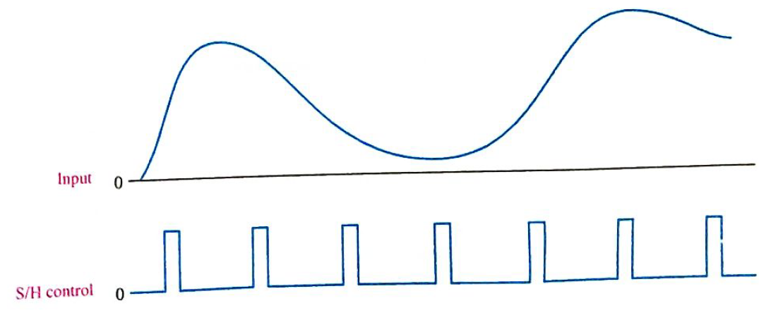
Repeat Problem 12 for the waveforms in Figure 21-51.
Expert Solution & Answer
Want to see the full answer?
Check out a sample textbook solution
Students have asked these similar questions
In the figure if the trigger angle of thyristors is a = 60 The waveform of the load current draw
Draw the output waveform and include the voltage value (silicon diode).
C
+8 V
R Vout
Vin 0
-8 V
+1₁
Please draw the input and out waveform. V-in = +10 to -10 peak to peak voltage.
Chapter 21 Solutions
Electronics Fundamentals: Circuits, Devices & Applications
Ch. 21 - A thermocouple can measure higher temperatures...Ch. 21 - Thermocouples are commonly used to measure body...Ch. 21 - An advantage of an RTD over a thermistor is that...Ch. 21 - Prob. 4TFQCh. 21 - A thermocouple signal conditioner must have high...Ch. 21 - Signal conditioning for temperature sensors...Ch. 21 - Prob. 7TFQCh. 21 - Absolute pressure is measured relative to the...Ch. 21 - In a sample-and-hold circuit, an analog value is...Ch. 21 - Prob. 10TFQ
Ch. 21 - A thermocouple a change in resistance for a change...Ch. 21 - In a thermocouple circuit, where each of the...Ch. 21 - A thermocouple signal conditioner is designed to...Ch. 21 - Prob. 4STCh. 21 - Prob. 5STCh. 21 - Prob. 6STCh. 21 - Prob. 7STCh. 21 - Prob. 8STCh. 21 - Prob. 9STCh. 21 - Prob. 10STCh. 21 - Prob. 11STCh. 21 - Prob. 12STCh. 21 - Prob. 13STCh. 21 - Prob. 14STCh. 21 - In an analog switch, the aperture time is the time...Ch. 21 - Prob. 16STCh. 21 - An analog signal must be sampled at a minimum rate...Ch. 21 - Prob. 18STCh. 21 - Prob. 19STCh. 21 - Prob. 20STCh. 21 - Prob. 21STCh. 21 - Three identical thermocouples are each exposed to...Ch. 21 - You have two thermocouples. One is a K type and...Ch. 21 - Determine the output voltage of the op-amp in...Ch. 21 - What should be the output voltage in Problem 3 if...Ch. 21 - Prob. 5PCh. 21 - Prob. 6PCh. 21 - Explain the difference in the results of Problems...Ch. 21 - Prob. 8PCh. 21 - A certain material being measured undergoes a...Ch. 21 - Explain how a strain gauge can be used to measure...Ch. 21 - Identify and compare the three symbols in Figure...Ch. 21 - Determine the output voltage waveform for the...Ch. 21 - Repeat Problem 12 for the waveforms in Figure...Ch. 21 - Name two ways an SCR can be placed in the...Ch. 21 - Sketch the VR waveform for the circuit in Figure...Ch. 21 - For the circuit in Figure 21-53, describe the...Ch. 21 - What change to the circuit in Figure 21-53 would...
Knowledge Booster


Learn more about
Need a deep-dive on the concept behind this application? Look no further. Learn more about this topic, electrical-engineering and related others by exploring similar questions and additional content below.Similar questions
- assume the circuit in figure 21-1 has a power factor of 68% an apparemt power of 300 VA and a frequency of 400 hz the capacitor has a capacitance of 4.7125 uf find the missing values.arrow_forwardcircuit elecronicarrow_forwardQ1/ Sketch the output waveform for the circuit. 15V RL Vo -15V Va 7V Input waveform wwarrow_forward
- draw the output voltage waveformarrow_forward5. In Figure, sketch the output waveform. What is the maximum positive voltage? The maximum negative? 30 V RLarrow_forwardA 10 V peak-to-peak sinusoidal voltage is applied across a silicon diode and series resistor. The maximum voltage across the diode isarrow_forward
- draw the output voltage waveformsarrow_forwardGiven Vi = 20V peak-to-peak, draw the output waveform for the said clamper circuit below:arrow_forward6. Determine the hysteresis voltage for each comparator in Figure 13-63. The maximum output levels are +1 V, R1 33 k) 150 k) R 18 k2 68 k2 (a) (b)arrow_forward
- Choose the correct waveform for the given Negative Edge triggered D- flipflop among the following: CIk Q CIk CIk- Darrow_forwardDetermine the output waveform: 10 5V -10+ TUT -5 25+ -15+ (A) (B) (C)arrow_forwardA step up chopper has input voltage of 200 V and output voltage of 600 V. If conducting time of thyristor chopper is 100 msec. Compute the pulse width of output voltage. A 100 msec B 50 msec C 150 msec D2 200 msecarrow_forward
arrow_back_ios
SEE MORE QUESTIONS
arrow_forward_ios
Recommended textbooks for you

Random Variables and Probability Distributions; Author: Dr Nic's Maths and Stats;https://www.youtube.com/watch?v=lHCpYeFvTs0;License: Standard Youtube License