
Electronics Fundamentals: Circuits, Devices & Applications
8th Edition
ISBN: 9780135072950
Author: Thomas L. Floyd, David Buchla
Publisher: Prentice Hall
expand_more
expand_more
format_list_bulleted
Videos
Textbook Question
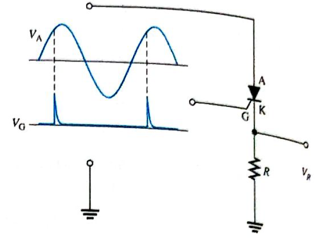
Chapter 21, Problem 15P
Sketch the
Expert Solution & Answer
Want to see the full answer?
Check out a sample textbook solution
Students have asked these similar questions
Clippers and Clampers. Determine the output waveform for each circuit. Show your solutions.
Difine the diodd and explain it’s basing conditions
Draw accurately the output waveform, show solution if needed.
Chapter 21 Solutions
Electronics Fundamentals: Circuits, Devices & Applications
Ch. 21 - A thermocouple can measure higher temperatures...Ch. 21 - Thermocouples are commonly used to measure body...Ch. 21 - An advantage of an RTD over a thermistor is that...Ch. 21 - Prob. 4TFQCh. 21 - A thermocouple signal conditioner must have high...Ch. 21 - Signal conditioning for temperature sensors...Ch. 21 - Prob. 7TFQCh. 21 - Absolute pressure is measured relative to the...Ch. 21 - In a sample-and-hold circuit, an analog value is...Ch. 21 - Prob. 10TFQ
Ch. 21 - A thermocouple a change in resistance for a change...Ch. 21 - In a thermocouple circuit, where each of the...Ch. 21 - A thermocouple signal conditioner is designed to...Ch. 21 - Prob. 4STCh. 21 - Prob. 5STCh. 21 - Prob. 6STCh. 21 - Prob. 7STCh. 21 - Prob. 8STCh. 21 - Prob. 9STCh. 21 - Prob. 10STCh. 21 - Prob. 11STCh. 21 - Prob. 12STCh. 21 - Prob. 13STCh. 21 - Prob. 14STCh. 21 - In an analog switch, the aperture time is the time...Ch. 21 - Prob. 16STCh. 21 - An analog signal must be sampled at a minimum rate...Ch. 21 - Prob. 18STCh. 21 - Prob. 19STCh. 21 - Prob. 20STCh. 21 - Prob. 21STCh. 21 - Three identical thermocouples are each exposed to...Ch. 21 - You have two thermocouples. One is a K type and...Ch. 21 - Determine the output voltage of the op-amp in...Ch. 21 - What should be the output voltage in Problem 3 if...Ch. 21 - Prob. 5PCh. 21 - Prob. 6PCh. 21 - Explain the difference in the results of Problems...Ch. 21 - Prob. 8PCh. 21 - A certain material being measured undergoes a...Ch. 21 - Explain how a strain gauge can be used to measure...Ch. 21 - Identify and compare the three symbols in Figure...Ch. 21 - Determine the output voltage waveform for the...Ch. 21 - Repeat Problem 12 for the waveforms in Figure...Ch. 21 - Name two ways an SCR can be placed in the...Ch. 21 - Sketch the VR waveform for the circuit in Figure...Ch. 21 - For the circuit in Figure 21-53, describe the...Ch. 21 - What change to the circuit in Figure 21-53 would...
Knowledge Booster


Learn more about
Need a deep-dive on the concept behind this application? Look no further. Learn more about this topic, electrical-engineering and related others by exploring similar questions and additional content below.Similar questions
- The positive peak value of output waveform for the given circuit diagram is. Bias voltage is 2 V, Diode is germanium) R1 I D, VOUT VIN VEIAS Earrow_forwardWhat is the average value of a half-wave rectified voltage with a peak value of 400 V? Draw its output waveform.arrow_forward20Vp Vout 9V 15V Draw output wave for this circuit mentioning maximum and minimum peak voltagesarrow_forward
- Determine the output voltage waveform of the circuit. Indicate the positive peak and negative peak.arrow_forwardTilt of the output waveform for the circuit is 1%. Given that input is a square wave ± 10 V, f = 2 kHz, diode cut-in voltage = 0.7, what is the relation between C and R?arrow_forwardIn a bridge full wave rectifier, the input sine wave is 25sin(30nt). The output frequency will be Select one: a. 15Hz b. 30Hz c. 25Hz d. 45Hzarrow_forward
- A 1 - ∅ full-wave rectifier is made by using thyristors. If the peak value of the sinusoidal input voltage is Vm and the value of the delay angle is 45 degree, find the average value of output voltage Select one: a. 0.65 VM b. 0.85 VM c. 0.45 VM d. 0.25 Vmarrow_forwardin a given figure, a signal is shown on a CRO screen. The CRO voltage per division (Volt/Div.) knob is set on 5 V, and Time per Division (Time/Div) knob is set on 10 ms. Calculate the signal amplitude and frequency. THEICN Ground LEVE NTENS TRO NP FOCUS VO ON INVERT NVERT CHI 40arrow_forward2. Draw and explain the difference between clipper circuit and clamper circuit output waveformarrow_forward
- Using an ideal diode, design a clamper circuit that result in the desired output waveform as shown in Figure Q7. Show overall analysis to justify the proposed design. 7. Vo Vi Designed Clamper Circuit - 3 V -20 - 43 V - Fiqure Q7 20arrow_forwardA sinusoidal voltage wave form of peak voltage í V and frequency f = 60Hz is applied to a bridge rectifier and to half wave rectifier separately. The Differences of average values and output frequencies arearrow_forward(C) Q/ Determine and find dc level output ? the vo and sketch wave form, Vi 20 Vo 20 22/ Draw input is aud the the claipper circuit when the Sinwave with (p-p) Cn 20U) diode (si) connected in Seriesarrow_forward
arrow_back_ios
SEE MORE QUESTIONS
arrow_forward_ios
Recommended textbooks for you
 Introductory Circuit Analysis (13th Edition)Electrical EngineeringISBN:9780133923605Author:Robert L. BoylestadPublisher:PEARSON
 Delmar's Standard Textbook Of ElectricityElectrical EngineeringISBN:9781337900348Author:Stephen L. HermanPublisher:Cengage Learning
 Programmable Logic ControllersElectrical EngineeringISBN:9780073373843Author:Frank D. PetruzellaPublisher:McGraw-Hill Education
 Fundamentals of Electric CircuitsElectrical EngineeringISBN:9780078028229Author:Charles K Alexander, Matthew SadikuPublisher:McGraw-Hill Education
 Electric Circuits. (11th Edition)Electrical EngineeringISBN:9780134746968Author:James W. Nilsson, Susan RiedelPublisher:PEARSON
 Engineering ElectromagneticsElectrical EngineeringISBN:9780078028151Author:Hayt, William H. (william Hart), Jr, BUCK, John A.Publisher:Mcgraw-hill Education,
Introductory Circuit Analysis (13th Edition)
Electrical Engineering
ISBN:9780133923605
Author:Robert L. Boylestad
Publisher:PEARSON
Delmar's Standard Textbook Of Electricity
Electrical Engineering
ISBN:9781337900348
Author:Stephen L. Herman
Publisher:Cengage Learning
Programmable Logic Controllers
Electrical Engineering
ISBN:9780073373843
Author:Frank D. Petruzella
Publisher:McGraw-Hill Education
Fundamentals of Electric Circuits
Electrical Engineering
ISBN:9780078028229
Author:Charles K Alexander, Matthew Sadiku
Publisher:McGraw-Hill Education
Electric Circuits. (11th Edition)
Electrical Engineering
ISBN:9780134746968
Author:James W. Nilsson, Susan Riedel
Publisher:PEARSON
Engineering Electromagnetics
Electrical Engineering
ISBN:9780078028151
Author:Hayt, William H. (william Hart), Jr, BUCK, John A.
Publisher:Mcgraw-hill Education,
Introduction to Logic Gates; Author: Computer Science;https://www.youtube.com/watch?v=fw-N9P38mi4;License: Standard youtube license