
Electronics Fundamentals: Circuits, Devices & Applications
8th Edition
ISBN: 9780135072950
Author: Thomas L. Floyd, David Buchla
Publisher: Prentice Hall
expand_more
expand_more
format_list_bulleted
Concept explainers
Videos
Textbook Question
Chapter 21, Problem 16P
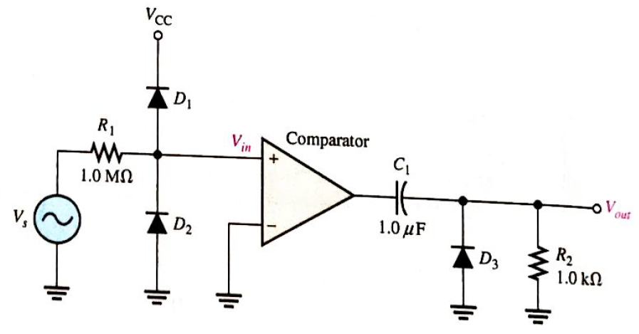
For the circuit in Figure 21-53, describe the waveform at the output of the comparator and at the output of the circuit in relation to the input. Assume the input is a 120 V rms sine wave the comparator and the power supply voltages for the comparator are
Expert Solution & Answer
Want to see the full answer?
Check out a sample textbook solution
Students have asked these similar questions
6. A full-wave rectified voltage waveform with peak value of 50 V is imposed on a 10 A dc constant
current load. What is the average power in the source? Draw the circuit and output waveforms.
A 60 Hz sinusoidal voltage is applied to a single-phase half-wave rectifier. The output of the rectifier would have a frequency of:
What is the average value of a half-wave rectified voltage with a peak value of 400 V? Draw its output waveform.
Chapter 21 Solutions
Electronics Fundamentals: Circuits, Devices & Applications
Ch. 21 - A thermocouple can measure higher temperatures...Ch. 21 - Thermocouples are commonly used to measure body...Ch. 21 - An advantage of an RTD over a thermistor is that...Ch. 21 - Prob. 4TFQCh. 21 - A thermocouple signal conditioner must have high...Ch. 21 - Signal conditioning for temperature sensors...Ch. 21 - Prob. 7TFQCh. 21 - Absolute pressure is measured relative to the...Ch. 21 - In a sample-and-hold circuit, an analog value is...Ch. 21 - Prob. 10TFQ
Ch. 21 - A thermocouple a change in resistance for a change...Ch. 21 - In a thermocouple circuit, where each of the...Ch. 21 - A thermocouple signal conditioner is designed to...Ch. 21 - Prob. 4STCh. 21 - Prob. 5STCh. 21 - Prob. 6STCh. 21 - Prob. 7STCh. 21 - Prob. 8STCh. 21 - Prob. 9STCh. 21 - Prob. 10STCh. 21 - Prob. 11STCh. 21 - Prob. 12STCh. 21 - Prob. 13STCh. 21 - Prob. 14STCh. 21 - In an analog switch, the aperture time is the time...Ch. 21 - Prob. 16STCh. 21 - An analog signal must be sampled at a minimum rate...Ch. 21 - Prob. 18STCh. 21 - Prob. 19STCh. 21 - Prob. 20STCh. 21 - Prob. 21STCh. 21 - Three identical thermocouples are each exposed to...Ch. 21 - You have two thermocouples. One is a K type and...Ch. 21 - Determine the output voltage of the op-amp in...Ch. 21 - What should be the output voltage in Problem 3 if...Ch. 21 - Prob. 5PCh. 21 - Prob. 6PCh. 21 - Explain the difference in the results of Problems...Ch. 21 - Prob. 8PCh. 21 - A certain material being measured undergoes a...Ch. 21 - Explain how a strain gauge can be used to measure...Ch. 21 - Identify and compare the three symbols in Figure...Ch. 21 - Determine the output voltage waveform for the...Ch. 21 - Repeat Problem 12 for the waveforms in Figure...Ch. 21 - Name two ways an SCR can be placed in the...Ch. 21 - Sketch the VR waveform for the circuit in Figure...Ch. 21 - For the circuit in Figure 21-53, describe the...Ch. 21 - What change to the circuit in Figure 21-53 would...
Knowledge Booster


Learn more about
Need a deep-dive on the concept behind this application? Look no further. Learn more about this topic, electrical-engineering and related others by exploring similar questions and additional content below.Similar questions
- In a bridge full wave rectifier, the input sine wave is 25sin(30nt). The output frequency will be Select one: a. 15Hz b. 30Hz c. 25Hz d. 45Hzarrow_forwardLIVE In the single-phase rectifier shown in figure Vs is sinusoidal with rms value of 120 V at 60 Hz, Ls = 1 mH and E = 150 V. Fromio waveform io peak value in ampere is io Ls 0000 A E is T4arrow_forwardA sinusoidal voltage wave form of peak voltage í V and frequency f = 60Hz is applied to a bridge rectifier and to half wave rectifier separately. The Differences of average values and output frequencies arearrow_forward
- Converter control in solar photovoltaicarrow_forwardCalculate the peak-to-peak inductor current ripple (in amperes) of a Buck converter assuming it operates in continuous current conduction mode. Circuit parameters are: Input voltage Vdc = 38 V, output voltage Vo = 17 V, PWM frequency fpwm = 50 kHz, inductor value 328 µH and capacitor value C = 10 µF. is S iL L I₂ Vac VA D VL ic C R₁ Please specify your answer in units of A to 2 decimal places. Varrow_forwardThe output frequency of a half-wave rectifier with a 60 Hz sinusoidal input is • (a) 30 Hz b) 60 Hz) e) 120) Hz d) 0 Hz)arrow_forward
- A single phase full converter feeds power to RLE load with R=10 ohm, L=10 mH and E=50 V, the ac source voltage is 230 V, 50 Hz. For continuous conduction, what is the average value of load current for firing angle delay of 600 ?arrow_forwardAn inductive load of 100 Ohm and 200mH connected in series to thyristor supplied by 200V dc source. The latching current of a thyristor is 45ma.and the duration of the firing pulse is 50us where the input supply voltage is 200V. Will the thyristor get fired?arrow_forwardIn the full-wave rectifier circuit of figure, the transformer has a turns ratio of 1:2. The transformer primary winding is connected across an AC source of 230V (rms), 50 Hz. The load resistor is 50ohms. For this circuit, determine the peak-to- peak ripple in the output voltage * Di i v2 = VmSin ot RL Vs(N V1 Vo + V3 = VmSin ot D2 Full-wave rectifier- Circuit operation during positive half cycle 460 V 207 V 325.3 V None of the above ell ellarrow_forward
arrow_back_ios
SEE MORE QUESTIONS
arrow_forward_ios
Recommended textbooks for you
 Introductory Circuit Analysis (13th Edition)Electrical EngineeringISBN:9780133923605Author:Robert L. BoylestadPublisher:PEARSON
 Delmar's Standard Textbook Of ElectricityElectrical EngineeringISBN:9781337900348Author:Stephen L. HermanPublisher:Cengage Learning
 Programmable Logic ControllersElectrical EngineeringISBN:9780073373843Author:Frank D. PetruzellaPublisher:McGraw-Hill Education
 Fundamentals of Electric CircuitsElectrical EngineeringISBN:9780078028229Author:Charles K Alexander, Matthew SadikuPublisher:McGraw-Hill Education
 Electric Circuits. (11th Edition)Electrical EngineeringISBN:9780134746968Author:James W. Nilsson, Susan RiedelPublisher:PEARSON
 Engineering ElectromagneticsElectrical EngineeringISBN:9780078028151Author:Hayt, William H. (william Hart), Jr, BUCK, John A.Publisher:Mcgraw-hill Education,
Introductory Circuit Analysis (13th Edition)
Electrical Engineering
ISBN:9780133923605
Author:Robert L. Boylestad
Publisher:PEARSON
Delmar's Standard Textbook Of Electricity
Electrical Engineering
ISBN:9781337900348
Author:Stephen L. Herman
Publisher:Cengage Learning
Programmable Logic Controllers
Electrical Engineering
ISBN:9780073373843
Author:Frank D. Petruzella
Publisher:McGraw-Hill Education
Fundamentals of Electric Circuits
Electrical Engineering
ISBN:9780078028229
Author:Charles K Alexander, Matthew Sadiku
Publisher:McGraw-Hill Education
Electric Circuits. (11th Edition)
Electrical Engineering
ISBN:9780134746968
Author:James W. Nilsson, Susan Riedel
Publisher:PEARSON
Engineering Electromagnetics
Electrical Engineering
ISBN:9780078028151
Author:Hayt, William H. (william Hart), Jr, BUCK, John A.
Publisher:Mcgraw-hill Education,
ME32 Wheatstone Bridge Method; Author: Lectures in Electrical Engineering;https://www.youtube.com/watch?v=p8iTTpzMR38;License: Standard YouTube License, CC-BY