
Electronics Fundamentals: Circuits, Devices & Applications
8th Edition
ISBN: 9780135072950
Author: Thomas L. Floyd, David Buchla
Publisher: Prentice Hall
expand_more
expand_more
format_list_bulleted
Concept explainers
Videos
Textbook Question
Chapter 20, Problem 7P
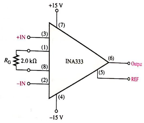
Specify what you must do to change the gain of the amplifier in Figure 20-46 to approximately 24.
Expert Solution & Answer
Want to see the full answer?
Check out a sample textbook solution
Students have asked these similar questions
What is Vcc in Amplifier
What will be the CMRR of an opamp if the value of the common mode gain is 100 and the value of the difference gain is 106?
File
Edit View
For an operational amplifier, the common mode gain is 0.1 and the differential gain is 1000.
What will be the CMRR of the opamp?
Chapter 20 Solutions
Electronics Fundamentals: Circuits, Devices & Applications
Ch. 20 - An instrumentation amplifier requires separate...Ch. 20 - Instrumentation amplifiers have excellent...Ch. 20 - The higher the gain of an instrumentation...Ch. 20 - An isolation amplifier is the same as an...Ch. 20 - An isolation amplifier is commonly used in...Ch. 20 - Prob. 6TFQCh. 20 - Prob. 7TFQCh. 20 - Prob. 8TFQCh. 20 - An active limiter circuit uses a diode in the...Ch. 20 - Prob. 10TFQ
Ch. 20 - To make a basic instrumentation amplifier, it...Ch. 20 - Prob. 2STCh. 20 - Prob. 3STCh. 20 - Prob. 4STCh. 20 - Prob. 5STCh. 20 - Prob. 6STCh. 20 - Prob. 7STCh. 20 - Prob. 8STCh. 20 - In an OTA, the transconductance is controlled by...Ch. 20 - Prob. 10STCh. 20 - An OTA is basically a voltage-to-current amplifier...Ch. 20 - Prob. 12STCh. 20 - When the + input of the clamper op-amp is...Ch. 20 - Prob. 14STCh. 20 - Prob. 15STCh. 20 - Determine the voltage gains of op-amps A1 and A2...Ch. 20 - Prob. 2PCh. 20 - Prob. 3PCh. 20 - Prob. 4PCh. 20 - What is the voltage gain of the INA333...Ch. 20 - Determine the approximate bandwidth of the...Ch. 20 - Specify what you must do to change the gain of the...Ch. 20 - Determine the value of RG in Figure 20-46 for a...Ch. 20 - The op-amp in the input stage of a 3656Â KG...Ch. 20 - Determine the total voltage gain of each 3656KG in...Ch. 20 - Specify how you would change the total gain of the...Ch. 20 - Prob. 12PCh. 20 - Specify how you would connect each amplifier in...Ch. 20 - A certain OTA has an input voltage of 10 mV and an...Ch. 20 - A certain CYLA with a transconductance of 5000S...Ch. 20 - The output voltage of a certain OTA with a load...Ch. 20 - Prob. 17PCh. 20 - Prob. 18PCh. 20 - The OTA in Figure 20-49 functions an amplitude...Ch. 20 - Determine the trigger points for the Schmitt...Ch. 20 - Determine the output voltage waveform for the...Ch. 20 - Describe the output waveform of each circuit in...Ch. 20 - Determine the output voltage for the clamping...Ch. 20 - Repeat Problem 23 for the clamping circuit in...Ch. 20 - Describe the output waveform for each circuit in...Ch. 20 - Determine the output waveform for the active...Ch. 20 - Show the output voltage for the zener diode...Ch. 20 - Repeat Problem 27 if the input is reduced to a...Ch. 20 - What is the ideal output voltage for a peak...Ch. 20 - Determine the load current in each circuit of...Ch. 20 - Devise a circuit for remotely sensing temperature...Ch. 20 - Prob. 33PCh. 20 - Open file P20-34 and determine the fault.Ch. 20 - Prob. 35PCh. 20 - Open file P20-36 and determine the fault.
Knowledge Booster


Learn more about
Need a deep-dive on the concept behind this application? Look no further. Learn more about this topic, electrical-engineering and related others by exploring similar questions and additional content below.Similar questions
- Distinguish between class A, class B and class C power amplifierarrow_forwardVIN = 300mV. Determine i, (the current sourced by the op amp) ? 1002 1002 +15 V B=10 100- Vo a. 0.30mA O b. 25.0mA Re call: for BJTA in the active ragion c. 6.00mA o d. 9.00mA e. 0.90mA :VEarrow_forwardVIN W -VOUT Figure 1 8) What trouble in the amplifier in Figure 1(c) could cause the voltage gain to drop to 1? A) the power is off B) Rj is open C) VOUT is grounded D) Rf is openarrow_forward
- It is the average of the two de currents that flows into the inverting and non- inverting inputs of an op-amp. O Input Bias Current O Input Offset Current O Quiescent Operating Current Feedback Currentarrow_forwardThe output levels of the open-loop op-amp are ±12V. VREF = +10V, R1 = 3 kQ and R2 = 1 kQ. Determine the output voltage, vo in Volt when vin = %3D OV. VREF R1 Vo R2 GND Vinarrow_forwardwhat makes instrumentation amplifer have greater CMRR compared to regular difference amplifer?arrow_forward
- Determine the voltage gain of the Op-Amp with a step by step compltete solutionarrow_forwardon For the circuit shown below, if the delay time of each stage is considered to be 50 ns, the oscillation frequency at the output will be almost MHZ HE VDD Voutarrow_forward1. Find Icand VCE in the pnp bias circuit. Assume Bpc = 100. VEE +10 V RE 470 N RB 10 k2 RC 330 N -10 V Vccarrow_forward
- For an opamp, the CMRR is 75 dB. If the differential gain is 4000, then what will be the common mode gain?arrow_forwardWrite a formula for Vout Input (Vin) +ve Op-amp R1 R2 Out 77770V (b) Non-inverting dc amplifierarrow_forwardAdiff-amp is blased with a constant-current source lo = 0.25mA that has an output resistance of Ro = 8MQ. The bipolar transistor parameters are ß = 100, VT = 0.025 V and VA =, Determine the differential-mode input resistance. O a. Rdi = 50 ka O b. Rdi = 30 ko Oc Rdi = 40 kQ O d. Rdi = 20 koarrow_forward
arrow_back_ios
SEE MORE QUESTIONS
arrow_forward_ios
Recommended textbooks for you
 Introductory Circuit Analysis (13th Edition)Electrical EngineeringISBN:9780133923605Author:Robert L. BoylestadPublisher:PEARSON
 Delmar's Standard Textbook Of ElectricityElectrical EngineeringISBN:9781337900348Author:Stephen L. HermanPublisher:Cengage Learning
 Programmable Logic ControllersElectrical EngineeringISBN:9780073373843Author:Frank D. PetruzellaPublisher:McGraw-Hill Education
 Fundamentals of Electric CircuitsElectrical EngineeringISBN:9780078028229Author:Charles K Alexander, Matthew SadikuPublisher:McGraw-Hill Education
 Electric Circuits. (11th Edition)Electrical EngineeringISBN:9780134746968Author:James W. Nilsson, Susan RiedelPublisher:PEARSON
 Engineering ElectromagneticsElectrical EngineeringISBN:9780078028151Author:Hayt, William H. (william Hart), Jr, BUCK, John A.Publisher:Mcgraw-hill Education,
Introductory Circuit Analysis (13th Edition)
Electrical Engineering
ISBN:9780133923605
Author:Robert L. Boylestad
Publisher:PEARSON
Delmar's Standard Textbook Of Electricity
Electrical Engineering
ISBN:9781337900348
Author:Stephen L. Herman
Publisher:Cengage Learning
Programmable Logic Controllers
Electrical Engineering
ISBN:9780073373843
Author:Frank D. Petruzella
Publisher:McGraw-Hill Education
Fundamentals of Electric Circuits
Electrical Engineering
ISBN:9780078028229
Author:Charles K Alexander, Matthew Sadiku
Publisher:McGraw-Hill Education
Electric Circuits. (11th Edition)
Electrical Engineering
ISBN:9780134746968
Author:James W. Nilsson, Susan Riedel
Publisher:PEARSON
Engineering Electromagnetics
Electrical Engineering
ISBN:9780078028151
Author:Hayt, William H. (william Hart), Jr, BUCK, John A.
Publisher:Mcgraw-hill Education,
Electrical Engineering: Ch 5: Operational Amp (2 of 28) Inverting Amplifier-Basic Operation; Author: Michel van Biezen;https://www.youtube.com/watch?v=x2xxOKOTwM4;License: Standard YouTube License, CC-BY