
Electronics Fundamentals: Circuits, Devices & Applications
8th Edition
ISBN: 9780135072950
Author: Thomas L. Floyd, David Buchla
Publisher: Prentice Hall
expand_more
expand_more
format_list_bulleted
Videos
Textbook Question
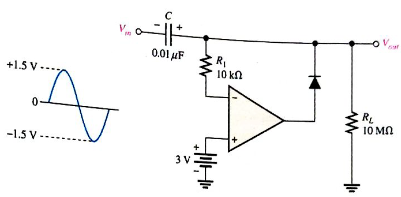
Chapter 20, Problem 24P
Repeat Problem 23 for the clamping circuit in Figure 20-53.
Expert Solution & Answer
Want to see the full answer?
Check out a sample textbook solution
Students have asked these similar questions
Natural commutation circuit is takes
place when
O Voltage across the device becomes negative
O Voltage across the device becomes positive
O gate current becomes zero
O anode current becomes Zero
commutation is
usually used in converters
O line
O load
O forced
O external - phase
11
The shown circuit represents
Q1
Vs
C
Load
buck converter
boost converter
full-bridge DC-DC converter
half-bridge DC-DC converter
Which of the signs in the figure is the one observed at the Amplitude Demodulator input?
I
IV
V
III
Chapter 20 Solutions
Electronics Fundamentals: Circuits, Devices & Applications
Ch. 20 - An instrumentation amplifier requires separate...Ch. 20 - Instrumentation amplifiers have excellent...Ch. 20 - The higher the gain of an instrumentation...Ch. 20 - An isolation amplifier is the same as an...Ch. 20 - An isolation amplifier is commonly used in...Ch. 20 - Prob. 6TFQCh. 20 - Prob. 7TFQCh. 20 - Prob. 8TFQCh. 20 - An active limiter circuit uses a diode in the...Ch. 20 - Prob. 10TFQ
Ch. 20 - To make a basic instrumentation amplifier, it...Ch. 20 - Prob. 2STCh. 20 - Prob. 3STCh. 20 - Prob. 4STCh. 20 - Prob. 5STCh. 20 - Prob. 6STCh. 20 - Prob. 7STCh. 20 - Prob. 8STCh. 20 - In an OTA, the transconductance is controlled by...Ch. 20 - Prob. 10STCh. 20 - An OTA is basically a voltage-to-current amplifier...Ch. 20 - Prob. 12STCh. 20 - When the + input of the clamper op-amp is...Ch. 20 - Prob. 14STCh. 20 - Prob. 15STCh. 20 - Determine the voltage gains of op-amps A1 and A2...Ch. 20 - Prob. 2PCh. 20 - Prob. 3PCh. 20 - Prob. 4PCh. 20 - What is the voltage gain of the INA333...Ch. 20 - Determine the approximate bandwidth of the...Ch. 20 - Specify what you must do to change the gain of the...Ch. 20 - Determine the value of RG in Figure 20-46 for a...Ch. 20 - The op-amp in the input stage of a 3656Â KG...Ch. 20 - Determine the total voltage gain of each 3656KG in...Ch. 20 - Specify how you would change the total gain of the...Ch. 20 - Prob. 12PCh. 20 - Specify how you would connect each amplifier in...Ch. 20 - A certain OTA has an input voltage of 10 mV and an...Ch. 20 - A certain CYLA with a transconductance of 5000S...Ch. 20 - The output voltage of a certain OTA with a load...Ch. 20 - Prob. 17PCh. 20 - Prob. 18PCh. 20 - The OTA in Figure 20-49 functions an amplitude...Ch. 20 - Determine the trigger points for the Schmitt...Ch. 20 - Determine the output voltage waveform for the...Ch. 20 - Describe the output waveform of each circuit in...Ch. 20 - Determine the output voltage for the clamping...Ch. 20 - Repeat Problem 23 for the clamping circuit in...Ch. 20 - Describe the output waveform for each circuit in...Ch. 20 - Determine the output waveform for the active...Ch. 20 - Show the output voltage for the zener diode...Ch. 20 - Repeat Problem 27 if the input is reduced to a...Ch. 20 - What is the ideal output voltage for a peak...Ch. 20 - Determine the load current in each circuit of...Ch. 20 - Devise a circuit for remotely sensing temperature...Ch. 20 - Prob. 33PCh. 20 - Open file P20-34 and determine the fault.Ch. 20 - Prob. 35PCh. 20 - Open file P20-36 and determine the fault.
Knowledge Booster


Learn more about
Need a deep-dive on the concept behind this application? Look no further. Learn more about this topic, electrical-engineering and related others by exploring similar questions and additional content below.Similar questions
- Design a Buck Converter with the Following Features. Input Voltage = 50 V Output Voltage = 20 V Switching Frequency=6 KHz Output Power = 300 W Efficiency =%85 Current fluctuationı <%10*Input current Output Voltage Ripple<%1*Output Voltagearrow_forwardA boost converter with an input voltage of 5 V dc and an output voltage of 8 V dc will have a duty cycle ofarrow_forwardA step up chopper has input voltage of 200 V and output voltage of 600 V. If conducting time of thyristor chopper is 100 msec. Compute the pulse width of output voltage. A 100 msec B 50 msec C 150 msec D2 200 msecarrow_forward
- For the given circuit, what is the minimum peak value of the output waveform if the input waveform is 10V square wave with switching time of 1 second? Assume that the input switches between +10V and -10V DC levels. O ov O -5V O - 20V O -10Varrow_forwardFor the given circuit, what is the minimum peak value of the output waveform if the input waveform is 10V square wave with switching time of 1 second? Assume that the input switches between +10V and -10V DC levels. O V -5 V -10 V -20 Varrow_forwardIn Staircase ramp type digital voltmeter contains DC amplifier with a fixed gain of . O 1000 100 O 10 1arrow_forward
- C/ Calculate load regulation of 7805 regulator has full load output voltage of 5.15 * V and no-load output voltage is 5.18 Varrow_forwardDraw the necessary waveforms. Inverting op-amp Re +10V Ri Vo Square Wave 741 Vị -10V GNDarrow_forwarddesign a triangular wave oscillator with oscillation frequency of (50 KHz) andtriangle wave has Vp-p = 6v with Vcc= 18v draw circuit and output waves (vo1 andVo2)arrow_forward
- Quèstion 29 Vcc The following biasing network is called IB Rc Vi HH Co RE Voltage divider biasing Emitter stabilized bias circuit Fixed bias configuration Collector feedback biasing aarrow_forward18. Determine the approximate values for each of the following quantities in Figure 12-67. (a) (b) ! (c) Vout (d) closed-loop gain FIGURE 12-67 R 22 kfl R, 2.2 klarrow_forward11. Identify each of the op-amp configurations in Figure 12-63 in www111 + (c)arrow_forward
arrow_back_ios
SEE MORE QUESTIONS
arrow_forward_ios
Recommended textbooks for you
 Introductory Circuit Analysis (13th Edition)Electrical EngineeringISBN:9780133923605Author:Robert L. BoylestadPublisher:PEARSON
 Delmar's Standard Textbook Of ElectricityElectrical EngineeringISBN:9781337900348Author:Stephen L. HermanPublisher:Cengage Learning
 Programmable Logic ControllersElectrical EngineeringISBN:9780073373843Author:Frank D. PetruzellaPublisher:McGraw-Hill Education
 Fundamentals of Electric CircuitsElectrical EngineeringISBN:9780078028229Author:Charles K Alexander, Matthew SadikuPublisher:McGraw-Hill Education
 Electric Circuits. (11th Edition)Electrical EngineeringISBN:9780134746968Author:James W. Nilsson, Susan RiedelPublisher:PEARSON
 Engineering ElectromagneticsElectrical EngineeringISBN:9780078028151Author:Hayt, William H. (william Hart), Jr, BUCK, John A.Publisher:Mcgraw-hill Education,
Introductory Circuit Analysis (13th Edition)
Electrical Engineering
ISBN:9780133923605
Author:Robert L. Boylestad
Publisher:PEARSON
Delmar's Standard Textbook Of Electricity
Electrical Engineering
ISBN:9781337900348
Author:Stephen L. Herman
Publisher:Cengage Learning
Programmable Logic Controllers
Electrical Engineering
ISBN:9780073373843
Author:Frank D. Petruzella
Publisher:McGraw-Hill Education
Fundamentals of Electric Circuits
Electrical Engineering
ISBN:9780078028229
Author:Charles K Alexander, Matthew Sadiku
Publisher:McGraw-Hill Education
Electric Circuits. (11th Edition)
Electrical Engineering
ISBN:9780134746968
Author:James W. Nilsson, Susan Riedel
Publisher:PEARSON
Engineering Electromagnetics
Electrical Engineering
ISBN:9780078028151
Author:Hayt, William H. (william Hart), Jr, BUCK, John A.
Publisher:Mcgraw-hill Education,
Resonance Circuits: LC Inductor-Capacitor Resonating Circuits; Author: Physics Videos by Eugene Khutoryansky;https://www.youtube.com/watch?v=Mq-PF1vo9QA;License: Standard YouTube License, CC-BY