
Electronics Fundamentals: Circuits, Devices & Applications
8th Edition
ISBN: 9780135072950
Author: Thomas L. Floyd, David Buchla
Publisher: Prentice Hall
expand_more
expand_more
format_list_bulleted
Concept explainers
Videos
Textbook Question
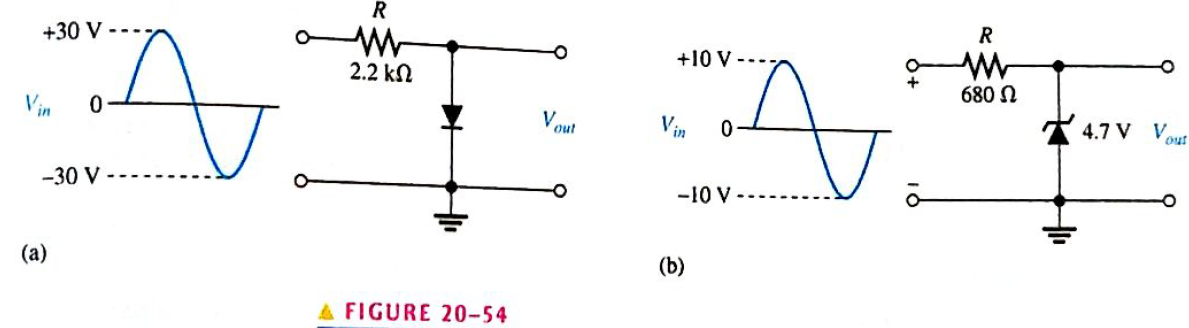
Chapter 20, Problem 25P
Describe the output waveform for each circuit in Figure 20-54.
Expert Solution & Answer
Want to see the full answer?
Check out a sample textbook solution
Students have asked these similar questions
20Vp
Vout
9V
15V
Draw output wave for this circuit
mentioning maximum and minimum peak
voltages
What is the active Band Stop Filter
The positive peak value of output waveform for the given circuit diagram is.
Bias voltage is 2 V, Diode is germanium)
(VPP of input is 18 V,
V
VouT
Chapter 20 Solutions
Electronics Fundamentals: Circuits, Devices & Applications
Ch. 20 - An instrumentation amplifier requires separate...Ch. 20 - Instrumentation amplifiers have excellent...Ch. 20 - The higher the gain of an instrumentation...Ch. 20 - An isolation amplifier is the same as an...Ch. 20 - An isolation amplifier is commonly used in...Ch. 20 - Prob. 6TFQCh. 20 - Prob. 7TFQCh. 20 - Prob. 8TFQCh. 20 - An active limiter circuit uses a diode in the...Ch. 20 - Prob. 10TFQ
Ch. 20 - To make a basic instrumentation amplifier, it...Ch. 20 - Prob. 2STCh. 20 - Prob. 3STCh. 20 - Prob. 4STCh. 20 - Prob. 5STCh. 20 - Prob. 6STCh. 20 - Prob. 7STCh. 20 - Prob. 8STCh. 20 - In an OTA, the transconductance is controlled by...Ch. 20 - Prob. 10STCh. 20 - An OTA is basically a voltage-to-current amplifier...Ch. 20 - Prob. 12STCh. 20 - When the + input of the clamper op-amp is...Ch. 20 - Prob. 14STCh. 20 - Prob. 15STCh. 20 - Determine the voltage gains of op-amps A1 and A2...Ch. 20 - Prob. 2PCh. 20 - Prob. 3PCh. 20 - Prob. 4PCh. 20 - What is the voltage gain of the INA333...Ch. 20 - Determine the approximate bandwidth of the...Ch. 20 - Specify what you must do to change the gain of the...Ch. 20 - Determine the value of RG in Figure 20-46 for a...Ch. 20 - The op-amp in the input stage of a 3656Â KG...Ch. 20 - Determine the total voltage gain of each 3656KG in...Ch. 20 - Specify how you would change the total gain of the...Ch. 20 - Prob. 12PCh. 20 - Specify how you would connect each amplifier in...Ch. 20 - A certain OTA has an input voltage of 10 mV and an...Ch. 20 - A certain CYLA with a transconductance of 5000S...Ch. 20 - The output voltage of a certain OTA with a load...Ch. 20 - Prob. 17PCh. 20 - Prob. 18PCh. 20 - The OTA in Figure 20-49 functions an amplitude...Ch. 20 - Determine the trigger points for the Schmitt...Ch. 20 - Determine the output voltage waveform for the...Ch. 20 - Describe the output waveform of each circuit in...Ch. 20 - Determine the output voltage for the clamping...Ch. 20 - Repeat Problem 23 for the clamping circuit in...Ch. 20 - Describe the output waveform for each circuit in...Ch. 20 - Determine the output waveform for the active...Ch. 20 - Show the output voltage for the zener diode...Ch. 20 - Repeat Problem 27 if the input is reduced to a...Ch. 20 - What is the ideal output voltage for a peak...Ch. 20 - Determine the load current in each circuit of...Ch. 20 - Devise a circuit for remotely sensing temperature...Ch. 20 - Prob. 33PCh. 20 - Open file P20-34 and determine the fault.Ch. 20 - Prob. 35PCh. 20 - Open file P20-36 and determine the fault.
Knowledge Booster


Learn more about
Need a deep-dive on the concept behind this application? Look no further. Learn more about this topic, electrical-engineering and related others by exploring similar questions and additional content below.Similar questions
- You are tasked to look for a converter circuit design that has the specifications tabulated in Table I. The aim is to produce an output voltage of 20 V which can be used to drive a load of 120 W. The converter must operate in CCM. Table I: Design Specifications Values 35 V Design Parameters Input voltage Switching frequency Output current ripple Output voltage ripple 60 kHz 5 % 1 % a) Sketch the final converter and label all parameter valuesarrow_forwardBriefly explain about Resonant CCM Boost Converter, zero current switching (ZCS) and zero voltage switching (ZVS)arrow_forwardPlease show all work for parts A,B, and C at the bottom of the Op-Amp.arrow_forward
- please write Details about Verification of series RL series circuitarrow_forwardDetermine the DC Voltage for the filtered bridge rectifier with a load as indicated in Figurearrow_forwardFirst quadrant operation of single phase fully controlled converter is called operation. of on oscillator is used in SMPS operation.arrow_forward
- Determine the output voltage waveform of the circuit. Indicate the positive peak and negative peak.arrow_forwardConsider the following figure. Represent the discrete samples into their corresponding hex values. Draw the analog signal. Image below:arrow_forward10. For the given circuit and input waveform, the peak value of the output is +30V. 20 V 10V -20 V a) True b) Falsearrow_forward
- You are tasked to look for a converter circuit design that has the specifications tabulated in Table I. The aim is to produce an output voltage of 20 V which can be used to drive a load of 120 W. The converter must operate in CCM. Table I: Design Specifications Design Parameters Input voltage Switching frequency Output current ripple Output voltage ripple Values 35 V 60 kHz 5 % 1% a) Sketch the final converter and label all parameter values b) Sketch the final operating waveforms and label all parameter values c) Determine Ve.min and Vemax- Check if the output voltage ripple matches with the design requirement.arrow_forwardDetermine the type of opamp circuit, the gain and the output voltage of the circuit for each of the operational amp circuits belowarrow_forward2. Draw and explain the difference between clipper circuit and clamper circuit output waveformarrow_forward
arrow_back_ios
SEE MORE QUESTIONS
arrow_forward_ios
Recommended textbooks for you
 Introductory Circuit Analysis (13th Edition)Electrical EngineeringISBN:9780133923605Author:Robert L. BoylestadPublisher:PEARSON
 Delmar's Standard Textbook Of ElectricityElectrical EngineeringISBN:9781337900348Author:Stephen L. HermanPublisher:Cengage Learning
 Programmable Logic ControllersElectrical EngineeringISBN:9780073373843Author:Frank D. PetruzellaPublisher:McGraw-Hill Education
 Fundamentals of Electric CircuitsElectrical EngineeringISBN:9780078028229Author:Charles K Alexander, Matthew SadikuPublisher:McGraw-Hill Education
 Electric Circuits. (11th Edition)Electrical EngineeringISBN:9780134746968Author:James W. Nilsson, Susan RiedelPublisher:PEARSON
 Engineering ElectromagneticsElectrical EngineeringISBN:9780078028151Author:Hayt, William H. (william Hart), Jr, BUCK, John A.Publisher:Mcgraw-hill Education,
Introductory Circuit Analysis (13th Edition)
Electrical Engineering
ISBN:9780133923605
Author:Robert L. Boylestad
Publisher:PEARSON
Delmar's Standard Textbook Of Electricity
Electrical Engineering
ISBN:9781337900348
Author:Stephen L. Herman
Publisher:Cengage Learning
Programmable Logic Controllers
Electrical Engineering
ISBN:9780073373843
Author:Frank D. Petruzella
Publisher:McGraw-Hill Education
Fundamentals of Electric Circuits
Electrical Engineering
ISBN:9780078028229
Author:Charles K Alexander, Matthew Sadiku
Publisher:McGraw-Hill Education
Electric Circuits. (11th Edition)
Electrical Engineering
ISBN:9780134746968
Author:James W. Nilsson, Susan Riedel
Publisher:PEARSON
Engineering Electromagnetics
Electrical Engineering
ISBN:9780078028151
Author:Hayt, William H. (william Hart), Jr, BUCK, John A.
Publisher:Mcgraw-hill Education,
Electrical Engineering: Ch 5: Operational Amp (2 of 28) Inverting Amplifier-Basic Operation; Author: Michel van Biezen;https://www.youtube.com/watch?v=x2xxOKOTwM4;License: Standard YouTube License, CC-BY