
Electronics Fundamentals: Circuits, Devices & Applications
8th Edition
ISBN: 9780135072950
Author: Thomas L. Floyd, David Buchla
Publisher: Prentice Hall
expand_more
expand_more
format_list_bulleted
Concept explainers
Videos
Textbook Question
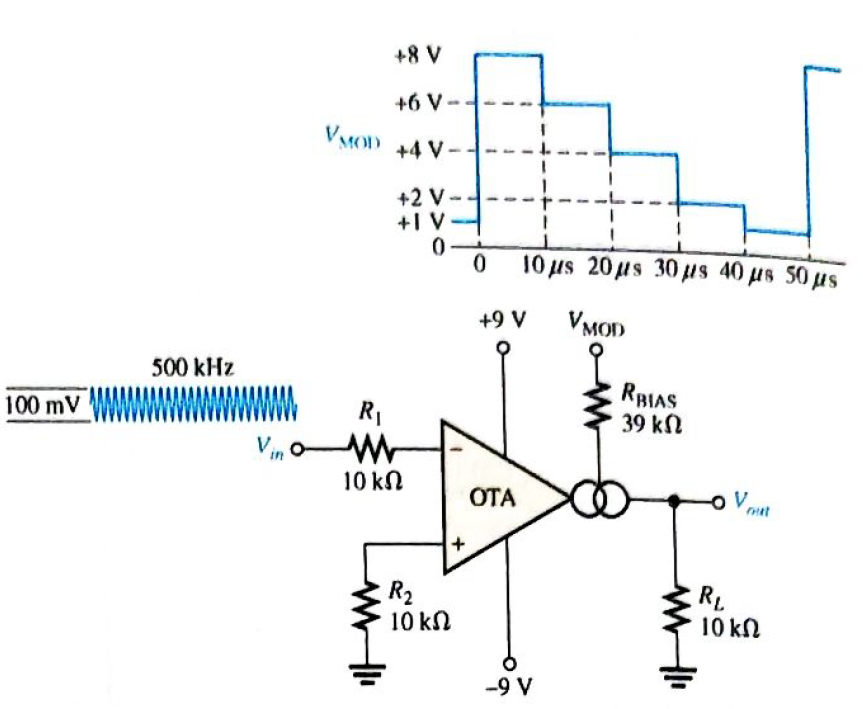
Chapter 20, Problem 19P
The OTA in Figure 20-49 functions an amplitude modulation circuit. Determine the output voltage waveform for the given input waveforms assuming
Expert Solution & Answer
Want to see the full answer?
Check out a sample textbook solution
Students have asked these similar questions
Draw low frequency small signal
FET model
Draw the AM waveform, if the modulating signal is a sine waveform and the percentage modulation is 100%.
2- For the circuit given below : Vin is a sine wave
Vinpp=18 V and Vref=-0.7 V, Assume
Vsat=±12V
Name the circuit and draw the input and output
waveforms .
Vo
Vin
Vref
Chapter 20 Solutions
Electronics Fundamentals: Circuits, Devices & Applications
Ch. 20 - An instrumentation amplifier requires separate...Ch. 20 - Instrumentation amplifiers have excellent...Ch. 20 - The higher the gain of an instrumentation...Ch. 20 - An isolation amplifier is the same as an...Ch. 20 - An isolation amplifier is commonly used in...Ch. 20 - Prob. 6TFQCh. 20 - Prob. 7TFQCh. 20 - Prob. 8TFQCh. 20 - An active limiter circuit uses a diode in the...Ch. 20 - Prob. 10TFQ
Ch. 20 - To make a basic instrumentation amplifier, it...Ch. 20 - Prob. 2STCh. 20 - Prob. 3STCh. 20 - Prob. 4STCh. 20 - Prob. 5STCh. 20 - Prob. 6STCh. 20 - Prob. 7STCh. 20 - Prob. 8STCh. 20 - In an OTA, the transconductance is controlled by...Ch. 20 - Prob. 10STCh. 20 - An OTA is basically a voltage-to-current amplifier...Ch. 20 - Prob. 12STCh. 20 - When the + input of the clamper op-amp is...Ch. 20 - Prob. 14STCh. 20 - Prob. 15STCh. 20 - Determine the voltage gains of op-amps A1 and A2...Ch. 20 - Prob. 2PCh. 20 - Prob. 3PCh. 20 - Prob. 4PCh. 20 - What is the voltage gain of the INA333...Ch. 20 - Determine the approximate bandwidth of the...Ch. 20 - Specify what you must do to change the gain of the...Ch. 20 - Determine the value of RG in Figure 20-46 for a...Ch. 20 - The op-amp in the input stage of a 3656Â KG...Ch. 20 - Determine the total voltage gain of each 3656KG in...Ch. 20 - Specify how you would change the total gain of the...Ch. 20 - Prob. 12PCh. 20 - Specify how you would connect each amplifier in...Ch. 20 - A certain OTA has an input voltage of 10 mV and an...Ch. 20 - A certain CYLA with a transconductance of 5000S...Ch. 20 - The output voltage of a certain OTA with a load...Ch. 20 - Prob. 17PCh. 20 - Prob. 18PCh. 20 - The OTA in Figure 20-49 functions an amplitude...Ch. 20 - Determine the trigger points for the Schmitt...Ch. 20 - Determine the output voltage waveform for the...Ch. 20 - Describe the output waveform of each circuit in...Ch. 20 - Determine the output voltage for the clamping...Ch. 20 - Repeat Problem 23 for the clamping circuit in...Ch. 20 - Describe the output waveform for each circuit in...Ch. 20 - Determine the output waveform for the active...Ch. 20 - Show the output voltage for the zener diode...Ch. 20 - Repeat Problem 27 if the input is reduced to a...Ch. 20 - What is the ideal output voltage for a peak...Ch. 20 - Determine the load current in each circuit of...Ch. 20 - Devise a circuit for remotely sensing temperature...Ch. 20 - Prob. 33PCh. 20 - Open file P20-34 and determine the fault.Ch. 20 - Prob. 35PCh. 20 - Open file P20-36 and determine the fault.
Knowledge Booster


Learn more about
Need a deep-dive on the concept behind this application? Look no further. Learn more about this topic, electrical-engineering and related others by exploring similar questions and additional content below.Similar questions
- design a triangular wave oscillator with oscillation frequency of (50 KHz) andtriangle wave has Vp-p = 6v with Vcc= 18v draw circuit and output waves (vo1 andVo2)arrow_forwardIn step-down regulator in Figure below, calculate the output voltage if the switching frequency is 76.923 kHz and the capacitor discharging time is 7 µs. What happen to the output voltage if the discharging time of the capacitor increased to 9 µs? Qi L VOUT VIN O ll RL Variable R2 pulse-width modulator Comparator Error signal VREF R3 D2arrow_forward) Briefly explain how the oscillation begin? RB VCC DISCHARGE. THRESHOLD TRIGGER ww www RESET VCC R SQ output 1 2/3 VCC 1/3VCC OUT VCC 0 m Capacitor Voltage I Output Voltagearrow_forward
- Which of the signs in the figure is the one observed at the Amplitude Demodulator input? I IV V IIIarrow_forwardthe time delay that must be provided by each stage in order to achieve an oscillation frequency of 5MHz, is: M₁ M₁ M Voo M₁ Vout x10%arrow_forwardDetermine the output waveform: 10 5V -10+ TUT -5 25+ -15+ (A) (B) (C)arrow_forward
- For the CRO display of a pulse waveform, the time/cm is on 25 ms/cm and the volt/cm switch is on 7 V/cm. The width of one complete cycle is 7.8cm and the height of the pulse is 4cm. Determine the frequency. O 5.13 O 0.02 O 0.36 0.00arrow_forward9. Sketch the output for the clipper circuts with the graph of the input sine wave. Label the clipping voltage level. (Or CLAMP crr) 4V- 2V 4V- BV- 4V- zv 4Varrow_forwardQ1/ Sketch the output waveform for the circuit. 15V RL Vo -15V Va 7V Input waveform wwarrow_forward
- For the given circuit, what is the minimum peak value of the output waveform if the input waveform is 10V square wave with switching time of 1 second? Assume that the input switches between +10V and -10V DC levels. O ov O -5V O - 20V O -10Varrow_forwardFor the given circuit, what is the minimum peak value of the output waveform if the input waveform is 10V square wave with switching time of 1 second? Assume that the input switches between +10V and -10V DC levels. O V -5 V -10 V -20 Varrow_forwardin a given figure, a signal is shown on a CRO screen. The CRO voltage per division (Volt/Div.) knob is set on 5 V, and Time per Division (Time/Div) knob is set on 10 ms. Calculate the signal amplitude and frequency. THEICN Ground LEVE NTENS TRO NP FOCUS VO ON INVERT NVERT CHI 40arrow_forward
arrow_back_ios
SEE MORE QUESTIONS
arrow_forward_ios
Recommended textbooks for you
 Introductory Circuit Analysis (13th Edition)Electrical EngineeringISBN:9780133923605Author:Robert L. BoylestadPublisher:PEARSON
 Delmar's Standard Textbook Of ElectricityElectrical EngineeringISBN:9781337900348Author:Stephen L. HermanPublisher:Cengage Learning
 Programmable Logic ControllersElectrical EngineeringISBN:9780073373843Author:Frank D. PetruzellaPublisher:McGraw-Hill Education
 Fundamentals of Electric CircuitsElectrical EngineeringISBN:9780078028229Author:Charles K Alexander, Matthew SadikuPublisher:McGraw-Hill Education
 Electric Circuits. (11th Edition)Electrical EngineeringISBN:9780134746968Author:James W. Nilsson, Susan RiedelPublisher:PEARSON
 Engineering ElectromagneticsElectrical EngineeringISBN:9780078028151Author:Hayt, William H. (william Hart), Jr, BUCK, John A.Publisher:Mcgraw-hill Education,
Introductory Circuit Analysis (13th Edition)
Electrical Engineering
ISBN:9780133923605
Author:Robert L. Boylestad
Publisher:PEARSON
Delmar's Standard Textbook Of Electricity
Electrical Engineering
ISBN:9781337900348
Author:Stephen L. Herman
Publisher:Cengage Learning
Programmable Logic Controllers
Electrical Engineering
ISBN:9780073373843
Author:Frank D. Petruzella
Publisher:McGraw-Hill Education
Fundamentals of Electric Circuits
Electrical Engineering
ISBN:9780078028229
Author:Charles K Alexander, Matthew Sadiku
Publisher:McGraw-Hill Education
Electric Circuits. (11th Edition)
Electrical Engineering
ISBN:9780134746968
Author:James W. Nilsson, Susan Riedel
Publisher:PEARSON
Engineering Electromagnetics
Electrical Engineering
ISBN:9780078028151
Author:Hayt, William H. (william Hart), Jr, BUCK, John A.
Publisher:Mcgraw-hill Education,
What is a Power Amplifier, And Do I Need One?; Author: Sweetwater;https://www.youtube.com/watch?v=2wkmSm4V00M;License: Standard Youtube License