
Electronics Fundamentals: Circuits, Devices & Applications
8th Edition
ISBN: 9780135072950
Author: Thomas L. Floyd, David Buchla
Publisher: Prentice Hall
expand_more
expand_more
format_list_bulleted
Concept explainers
Videos
Textbook Question
Chapter 20, Problem 6P
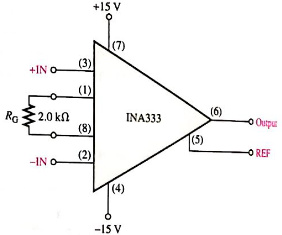
Determine the approximate bandwidth of the amplifier in Figure 20-46. Use the graph in Figure 20-6.
Expert Solution & Answer
Want to see the full answer?
Check out a sample textbook solution
Students have asked these similar questions
Input voltages v1 = 3 + 0.00075 sin wt V and v2 = 3-0.00075 sin wt
V are applied to a differential amplifier. The differential mode gain is
Ad = 250 and CMRRdB = 80 dB. Determine the output voltage
Ry= 100ka
C= OL047pF
RI
10kO
15V
R2
10k2,
1. Mention the phase difference between the input and output waveforms?
2. Calculate the Vout of the output waveforms?
3. Calculate the comer frequency of output waveform?
4. Draw the input and output waveforms of integrator.
II. K type thermocouple having a range of 0- 350 °C and a sensitivity of 40 µV/°C. The
signal is connected to an instrumentation amplifier before interfacing it with 5V analog
to digital converter. Design a suitable instrumentation amplifier circuit.
Vsupply
thermocouple
Vout
Instrum
Amp
Dout
ADC
Chapter 20 Solutions
Electronics Fundamentals: Circuits, Devices & Applications
Ch. 20 - An instrumentation amplifier requires separate...Ch. 20 - Instrumentation amplifiers have excellent...Ch. 20 - The higher the gain of an instrumentation...Ch. 20 - An isolation amplifier is the same as an...Ch. 20 - An isolation amplifier is commonly used in...Ch. 20 - Prob. 6TFQCh. 20 - Prob. 7TFQCh. 20 - Prob. 8TFQCh. 20 - An active limiter circuit uses a diode in the...Ch. 20 - Prob. 10TFQ
Ch. 20 - To make a basic instrumentation amplifier, it...Ch. 20 - Prob. 2STCh. 20 - Prob. 3STCh. 20 - Prob. 4STCh. 20 - Prob. 5STCh. 20 - Prob. 6STCh. 20 - Prob. 7STCh. 20 - Prob. 8STCh. 20 - In an OTA, the transconductance is controlled by...Ch. 20 - Prob. 10STCh. 20 - An OTA is basically a voltage-to-current amplifier...Ch. 20 - Prob. 12STCh. 20 - When the + input of the clamper op-amp is...Ch. 20 - Prob. 14STCh. 20 - Prob. 15STCh. 20 - Determine the voltage gains of op-amps A1 and A2...Ch. 20 - Prob. 2PCh. 20 - Prob. 3PCh. 20 - Prob. 4PCh. 20 - What is the voltage gain of the INA333...Ch. 20 - Determine the approximate bandwidth of the...Ch. 20 - Specify what you must do to change the gain of the...Ch. 20 - Determine the value of RG in Figure 20-46 for a...Ch. 20 - The op-amp in the input stage of a 3656Â KG...Ch. 20 - Determine the total voltage gain of each 3656KG in...Ch. 20 - Specify how you would change the total gain of the...Ch. 20 - Prob. 12PCh. 20 - Specify how you would connect each amplifier in...Ch. 20 - A certain OTA has an input voltage of 10 mV and an...Ch. 20 - A certain CYLA with a transconductance of 5000S...Ch. 20 - The output voltage of a certain OTA with a load...Ch. 20 - Prob. 17PCh. 20 - Prob. 18PCh. 20 - The OTA in Figure 20-49 functions an amplitude...Ch. 20 - Determine the trigger points for the Schmitt...Ch. 20 - Determine the output voltage waveform for the...Ch. 20 - Describe the output waveform of each circuit in...Ch. 20 - Determine the output voltage for the clamping...Ch. 20 - Repeat Problem 23 for the clamping circuit in...Ch. 20 - Describe the output waveform for each circuit in...Ch. 20 - Determine the output waveform for the active...Ch. 20 - Show the output voltage for the zener diode...Ch. 20 - Repeat Problem 27 if the input is reduced to a...Ch. 20 - What is the ideal output voltage for a peak...Ch. 20 - Determine the load current in each circuit of...Ch. 20 - Devise a circuit for remotely sensing temperature...Ch. 20 - Prob. 33PCh. 20 - Open file P20-34 and determine the fault.Ch. 20 - Prob. 35PCh. 20 - Open file P20-36 and determine the fault.
Knowledge Booster


Learn more about
Need a deep-dive on the concept behind this application? Look no further. Learn more about this topic, electrical-engineering and related others by exploring similar questions and additional content below.Similar questions
- Show the effect of sampling time on the characteristic of ZOH. digital to analog converterarrow_forwardfind the output voltage Vout (s) for the following two circuits: Rf R1 in Vout а) Rf R1 Vin V. out b)arrow_forward33nF HI +1₁ 27 k H + 10 k 10 k Vo Opamp is 741 with Vcc = 15V and VEE = -15V What is the frequency of oscillation of the Astable Multivibrator circuit. Sketch the Vo and show complete details.arrow_forward
- on For the circuit shown below, if the delay time of each stage is considered to be 50 ns, the oscillation frequency at the output will be almost MHZ HE VDD Voutarrow_forward35. Determine the midrange gain in dB of each amplifier in Figure 12-72. Are these open-loop or closed-loop gains? Rp 68 k) R 2.2 kN R 220 kN R; 15 k. (a) (b)arrow_forward92 ۱ ۹:۱ ص Qs= 1107 and Qp= 1041 Qs= 1207 and Qp= 1241 Qs= 1007 and Qp= 1041 Qs= 1107 and Qp= 1141 In the figure shown below we can find output current is equal to.. . if the input voltage is equal to 12 mv 12 kO 12 ka 6 ka No option is correct 10 = 32 uA 10 = 34 uA 10 = 38 uA 10 = 36 uA In the fig. shown below we can find the higher critical frequency due to the inputarrow_forward
- II. K type thermocouple having a range of 0 – 350 °C and a sensitivity of 40 µV/°C. The signal is connected to an instrumentation amplifier before interfacing it with 5V analog to digital converter. Design a suitable instrumentation amplifier circuit. Vsupply thermocouple Vout Instrum. op Amp ADC -Doutarrow_forwardcurrent gain and power gainarrow_forwardHow does the output voltage vary when the capacitance is doubled in integrator operational amplifier citcuit?arrow_forward
- The upper cutoff frequency of this amplifoer is 22KHz. The output at that frequency is 6.71V p-p. What is the output voltage of 220kHz.arrow_forwardR VR E + Figure 20-2arrow_forwardIn an Inverting amplifier the output voltage is a. Always positive b. none of the above c. Always negetive d. Depending upon input voltage positive or negetivearrow_forward
arrow_back_ios
SEE MORE QUESTIONS
arrow_forward_ios
Recommended textbooks for you
 Introductory Circuit Analysis (13th Edition)Electrical EngineeringISBN:9780133923605Author:Robert L. BoylestadPublisher:PEARSON
 Delmar's Standard Textbook Of ElectricityElectrical EngineeringISBN:9781337900348Author:Stephen L. HermanPublisher:Cengage Learning
 Programmable Logic ControllersElectrical EngineeringISBN:9780073373843Author:Frank D. PetruzellaPublisher:McGraw-Hill Education
 Fundamentals of Electric CircuitsElectrical EngineeringISBN:9780078028229Author:Charles K Alexander, Matthew SadikuPublisher:McGraw-Hill Education
 Electric Circuits. (11th Edition)Electrical EngineeringISBN:9780134746968Author:James W. Nilsson, Susan RiedelPublisher:PEARSON
 Engineering ElectromagneticsElectrical EngineeringISBN:9780078028151Author:Hayt, William H. (william Hart), Jr, BUCK, John A.Publisher:Mcgraw-hill Education,
Introductory Circuit Analysis (13th Edition)
Electrical Engineering
ISBN:9780133923605
Author:Robert L. Boylestad
Publisher:PEARSON
Delmar's Standard Textbook Of Electricity
Electrical Engineering
ISBN:9781337900348
Author:Stephen L. Herman
Publisher:Cengage Learning
Programmable Logic Controllers
Electrical Engineering
ISBN:9780073373843
Author:Frank D. Petruzella
Publisher:McGraw-Hill Education
Fundamentals of Electric Circuits
Electrical Engineering
ISBN:9780078028229
Author:Charles K Alexander, Matthew Sadiku
Publisher:McGraw-Hill Education
Electric Circuits. (11th Edition)
Electrical Engineering
ISBN:9780134746968
Author:James W. Nilsson, Susan Riedel
Publisher:PEARSON
Engineering Electromagnetics
Electrical Engineering
ISBN:9780078028151
Author:Hayt, William H. (william Hart), Jr, BUCK, John A.
Publisher:Mcgraw-hill Education,
Multistage Transistor Audio Amplifier Circuit; Author: The Organic Chemistry Tutor;https://www.youtube.com/watch?v=LJrL9N9uhkE;License: Standard Youtube License