
Mechanics of Materials, 7th Edition
7th Edition
ISBN: 9780073398235
Author: Ferdinand P. Beer, E. Russell Johnston Jr., John T. DeWolf, David F. Mazurek
Publisher: McGraw-Hill Education
expand_more
expand_more
format_list_bulleted
Videos
Textbook Question
Chapter 1.5, Problem 53P
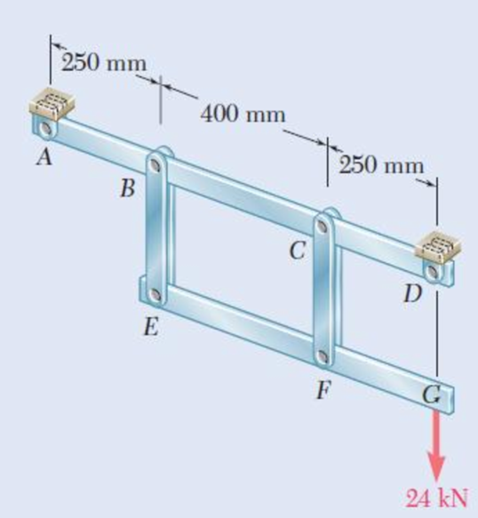
Each of the two vertical links CF connecting the two horizontal members AD and EG has a 10 × 40-mm uniform rectangular cross section and is made of a steel with an ultimate strength in tension of 400 MPa, while each of the pins at C and F has a 20-mm diameter and are made of a steel with an ultimate strength in shear of 150 MPa. Determine the overall factor of safety for the links CF and the pins connecting them to the horizontal members.
Fig. P1.53
Expert Solution & Answer
Want to see the full answer?
Check out a sample textbook solution
Students have asked these similar questions
250 mm
400 mm
1.53 Each of the two vertical links CF connecting the two horizontal
members AD and EG has a 10 x 40-mm uniform rectangular
cross section and is made of a steel with an ultimate strength in
tension of 400 MPa, while each of the pins at C and F has a
20-mm diameter and are made of a steel with an ultimate strength
in shear of 150 MPa. Determine the overall factor of safety for the
links CF and the pins connecting them to the horizontal
members.
A
250 mm
D
E
F
24 kN
16. Each of the two vertical links CF connecting the two horizontal members AD and EG has a
uniform rectangular cross section ¼ in. thick and 1 in. wide, and is made of steel with an ultimate
strength in tension of 60 ksi. The pins at C and F each have a ½ in. diameter and are made of a
steel with an ultimate strength in shear of 25 ksi. Determine the overall factor of safety for the
links CF and the pins connecting them to the horizontal members.
10 in.
16 in.
10 in.
2 kips
In the steel structure shown, a 6-mm-diameter pin is used at C and10-mm-diameter pins are used at B and D. The ultimate shearing stress is 150 MPa at all connections, and the ultimate normal stress is 400 MPa in link BD. Knowing that a factor of safety of 3.0 is desired,determine the largest load P that can be applied at A. Note that link BD is not reinforced around the pin holes.
Chapter 1 Solutions
Mechanics of Materials, 7th Edition
Ch. 1.2 - Two solid cylindrical rods AB and BC are welded...Ch. 1.2 - Two solid cylindrical rods AB and BC are welded...Ch. 1.2 - Two solid cylindrical rods AB and BC are welded...Ch. 1.2 - Two solid cylindrical rods AB and BC are welded...Ch. 1.2 - A strain gage located at C on the surface of bone...Ch. 1.2 - Two brass rods AB and BC, each of uniform...Ch. 1.2 - Each of the four vertical links has an 8 36-mm...Ch. 1.2 - Link AC has a uniform rectangular cross section 18...Ch. 1.2 - Three forces, each of magnitude P = 4 kN, are...Ch. 1.2 - Link BD consists of a single bar 1 in. wide and 12...
Ch. 1.2 - For the Pratt bridge truss and loading shown,...Ch. 1.2 - The frame shown consists of four wooden members,...Ch. 1.2 - An aircraft tow bar is positioned by means of a...Ch. 1.2 - Two hydraulic cylinders are used to control the...Ch. 1.2 - Determine the diameter of the largest circular...Ch. 1.2 - Two wooden planks, each 12 in. thick and 9 in....Ch. 1.2 - When the force P reached 1600 lb, the wooden...Ch. 1.2 - A load P is applied to a steel rod supported as...Ch. 1.2 - The axial force in the column supporting the...Ch. 1.2 - Three wooden planks are fastened together by a...Ch. 1.2 - A 40-kN axial load is applied to a short wooden...Ch. 1.2 - An axial load P is supported by a short W8 40...Ch. 1.2 - Link AB, of width b = 2 in. and thickness t=14...Ch. 1.2 - Determine the largest load P that can be applied...Ch. 1.2 - Knowing that = 40 and P = 9 kN, determine (a) the...Ch. 1.2 - The hydraulic cylinder CF, which partially...Ch. 1.2 - For the assembly and loading of Prob. 1.7,...Ch. 1.2 - Two identical linkage-and-hydraulic-cylinder...Ch. 1.5 - Two wooden members of uniform rectangular cross...Ch. 1.5 - Two wooden members of uniform rectangular cross...Ch. 1.5 - The 1.4-kip load P is supported by two wooden...Ch. 1.5 - Two wooden members of uniform cross section are...Ch. 1.5 - A centric load P is applied to the granite block...Ch. 1.5 - A 240-kip load P is applied to the granite block...Ch. 1.5 - A steel pipe of 400-mm outer diameter is...Ch. 1.5 - A steel pipe of 400-mm outer diameter is...Ch. 1.5 - A steel loop ABCD of length 5 ft and of 38-in....Ch. 1.5 - Link BC is 6 mm thick, has a width w = 25 mm, and...Ch. 1.5 - Link BC is 6 mm thick and is made of a steel with...Ch. 1.5 - Members AB and BC of the truss shown are made of...Ch. 1.5 - Members AB and BC of the truss shown are made of...Ch. 1.5 - Link AB is to be made of a steel for which the...Ch. 1.5 - Two wooden members are joined by plywood splice...Ch. 1.5 - For the joint and loading of Prob. 1.43, determine...Ch. 1.5 - Three 34-in.-diameter steel bolts are to be used...Ch. 1.5 - Three steel bolts are to be used to attach the...Ch. 1.5 - A load P is supported as shown by a steel pin that...Ch. 1.5 - A load P is supported as shown by a steel pin that...Ch. 1.5 - A steel plate 14 in. thick is embedded in a...Ch. 1.5 - Determine the factor of safety for the cable...Ch. 1.5 - Link AC is made of a steel with a 65-ksi ultimate...Ch. 1.5 - Solve Prob. 1.51, assuming that the structure has...Ch. 1.5 - Each of the two vertical links CF connecting the...Ch. 1.5 - Solve Prob. 1.53, assuming that the pins at C and...Ch. 1.5 - In the structure shown, an 8-mm-diameter pin is...Ch. 1.5 - In an alternative design for the structure of...Ch. 1.5 - Prob. 57PCh. 1.5 - The Load and Resistance Factor Design method is to...Ch. 1 - In the marine crane shown, link CD is known to...Ch. 1 - Two horizontal 5-kip forces are applied to pin B...Ch. 1 - For the assembly and loading of Prob. 1.60,...Ch. 1 - Two steel plates are to be held together by means...Ch. 1 - A couple M of magnitude 1500 N m is applied to...Ch. 1 - Knowing that link DE is 18 in. thick and 1 in....Ch. 1 - A 58-in.-diameter steel rod AB is fitted to a...Ch. 1 - In the steel structure shown, a 6-mm-diameter pin...Ch. 1 - Prob. 67RPCh. 1 - A force P is applied as shown to a steel...Ch. 1 - The two portions of member AB are glued together...Ch. 1 - The two portions of member AB are glued together...
Knowledge Booster


Learn more about
Need a deep-dive on the concept behind this application? Look no further. Learn more about this topic, mechanical-engineering and related others by exploring similar questions and additional content below.Similar questions
- In the steel structure shown, a 6-mm-diameter pin is used at C and 12-mm-diameter pins are used at B and D. The ultimate shearing stress is 150 MPa at all connections, and the ultimate normal stress is 350 MPa in link BD. Knowing that a factor of safety of 3.0 is desired, determine the largest load P that can be applied at A. Note that link BD is not reinforced around the pin holes. The largest load P that can be applied at A is kN.arrow_forwardIn the structure shown, an 8-mm-diameter pin is used at A, and 12-mm-diameter pins are used at B and D. Knowing that the ultimate shearing stress is 100 MPa at all connections and that the ultimate normal stress is 250 MPa in each of the two links joining B and D, determine the allowable load P if an overall factor of safety of 2.6 is desired.arrow_forwardIn the structure shown, an 8-mm diameter pin is used at A, and 12- mm diameter pins are used at B and D. Knowing that the ultimate shearing stresses is 100 MPa at all connections and that the ultimate normal stress is 250 MPa in each of the two links joining B and D, determine the allowable load P if an overall factor of safety of 3.0 is desired.arrow_forward
- In the structure shown, an 8-mm-diameter pin is used at A and 12 mmdiameter pins are used at B and D. Knowing that the ultimate shearingstress is 100 MPa at all connections and the ultimate normal stress is 250 MPa in each of the two links joining B and D, determine the allowable load P if an overall factor of safety of 3.0 is desired.arrow_forwardTwo links BF are made of steel with a 450-MPa ultimate normal stress and has a 6x12–mm uniform rectangular cross section. Links BF are connected to members ABD and CDEF by 8-mm diameter pins; ABD and CDEF are connected together by a 10-mm diameter pin; CDEF is connected to the support by a 10-mm diameter pin; all of the pins are made of steel with a 170 MPa ultimate shearing stress. Knowing that a factor of safety of 3 is desired, determine the largest load P that may be appliedarrow_forwardProblem # 6 A bolt with a diameter of 24 mm is used to join two steel plates together. The plates are subjected to a load of 120 kN. Determine the minimum number of bolts needed to avoid shear failure if the allowable shear stress in the bolts is 150 MPa.arrow_forward
- 15. In the steel structure shown, a 6-mm-diamter pin is used at C and 10-mm-diameter pins are used at B and D. The ultimate shearing stress is 150 MPa at all connections, and the ultimate normal stress is 400 MPa in link BD. Knowing that a factor of safety is 3.0 is desired, determine the largest load P that can be applied at A. Note that link BD is not reinforced around the pin holes. Front view 18 mm 6 mm 120 mm- Side view 160 mm Top viewarrow_forwardA 20 mm diameter rod BC has flat ends of 20 mm x 40 mm rectangular cross section, while the boom AB has a 30 x 50 mm rectangular cross section and is fitted with a clevis at the end B. Both members are connected at B by a pin from which the 30 kN load is suspended by means of a U-Shaped bracket. Boom AB is supported at A by a pin fitted into a double bracket, while rod BC is connected at C to a single bracket. All pins are 25 mm diameter. Determine the normal stresses in members AB and BC; shearing stresses and bearing stresses at A, B and C.arrow_forwardA 20 mm diameter steel rod passes concentrically through a bronze tube (200+SN) mm long, 50 mm external diameter and 40 mm internal diameter. The ends of the steel rod are threaded and provided with nuts and washers which are adjusted initially so that there is no end play at 25°C.. 1. Assuming that there is no change in the thickness of the washers, if the stress produced in the steel is (200+SN) MN/m2 when one of the nuts is tightened, the pitch of the thread being 1 mm. Find the number of turns for the nut and stress in bronze tube.2. If the temperature of the steel and bronze is then raised to 4O°C find the changes that will occur in the stresses in both materials. The coefficient of linear expansion per C is 10 x10-6 for steel and 17 x10-6 for bronze. E for steel = 210 GN/m2. E %3D for bronze = 100 GN/m2.. Note: SN = %3D Student number Student Number =32arrow_forward
- Problem 1. The steel tie bar shown is to be designed to carry a tension force of magnitude P = 130KN when bolted between double brackets at A and B. The bar will be fabricated from 25-mm-thick plate stock. For the grade of steel to be used, the maximum allowable stresses are: o = 170 MPa, t = 110 MPa, op = 370 MPa. Design the tie bar by determining the required values of: a. the diameter d of the bolt, b. the dimension b at each end of the bar, c. the dimensionh of the bar.arrow_forward1. The structure is used to support a distributed load of w = 15 kN/m. The bolts at A, B, and C each have a diameter of 16 mm and each bolt is used in a double shear connection. The cross-sectional area of axial member (1) is 3,080 mm^2. The allowable stress in axial member (1) is 50 MPa and 280 MPa for the bolts. Determine the factor of safety with respect to the specified allowable stresses for axial member (1) and bolt at C.arrow_forwardTwo wooden members of uniform rectangular cross section of sides a = 100 mm and b = 60 mm are joined by a simple glued joint as shown. Knowing that the ultimate stresses for the joint are σU =1.26 MPa in tension and τU = 1.50 MPa in shear and that P =6 kN, determine the factor of safety for the joint when (a) α =20°,(b) α =35°, (c) α =45°. For each of these values of α, also determine whether the joint will fail in tension or in shear if P is increased until rupture occurs.arrow_forward
arrow_back_ios
SEE MORE QUESTIONS
arrow_forward_ios
Recommended textbooks for you
 Elements Of ElectromagneticsMechanical EngineeringISBN:9780190698614Author:Sadiku, Matthew N. O.Publisher:Oxford University Press
 Mechanics of Materials (10th Edition)Mechanical EngineeringISBN:9780134319650Author:Russell C. HibbelerPublisher:PEARSON
 Thermodynamics: An Engineering ApproachMechanical EngineeringISBN:9781259822674Author:Yunus A. Cengel Dr., Michael A. BolesPublisher:McGraw-Hill Education
 Control Systems EngineeringMechanical EngineeringISBN:9781118170519Author:Norman S. NisePublisher:WILEY
 Mechanics of Materials (MindTap Course List)Mechanical EngineeringISBN:9781337093347Author:Barry J. Goodno, James M. GerePublisher:Cengage Learning
 Engineering Mechanics: StaticsMechanical EngineeringISBN:9781118807330Author:James L. Meriam, L. G. Kraige, J. N. BoltonPublisher:WILEY
Elements Of Electromagnetics
Mechanical Engineering
ISBN:9780190698614
Author:Sadiku, Matthew N. O.
Publisher:Oxford University Press
Mechanics of Materials (10th Edition)
Mechanical Engineering
ISBN:9780134319650
Author:Russell C. Hibbeler
Publisher:PEARSON
Thermodynamics: An Engineering Approach
Mechanical Engineering
ISBN:9781259822674
Author:Yunus A. Cengel Dr., Michael A. Boles
Publisher:McGraw-Hill Education
Control Systems Engineering
Mechanical Engineering
ISBN:9781118170519
Author:Norman S. Nise
Publisher:WILEY
Mechanics of Materials (MindTap Course List)
Mechanical Engineering
ISBN:9781337093347
Author:Barry J. Goodno, James M. Gere
Publisher:Cengage Learning
Engineering Mechanics: Statics
Mechanical Engineering
ISBN:9781118807330
Author:James L. Meriam, L. G. Kraige, J. N. Bolton
Publisher:WILEY
An Introduction to Stress and Strain; Author: The Efficient Engineer;https://www.youtube.com/watch?v=aQf6Q8t1FQE;License: Standard YouTube License, CC-BY