
Videos
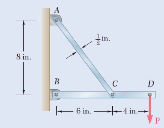
Link AC is made of a steel with a 65-ksi ultimate normal stress and has a
Fig. P1.51
Want to see the full answer?
Check out a sample textbook solution
Chapter 1 Solutions
Mechanics of Materials, 7th Edition


- Two ropes are used to hoist a 610 Ib engine/transmission assembly as shown. The rope is anchored at C around the center part of the pin shown, causing the pin to experience a state of double shear. There is a frictionless pulley at A. The normal stress in the rope must not be allowed to exceed 12 ksi, and the shearing stress in the pin must not exceed 23 ksi. When the hoist is in the position given by: a = 41 in b = 13 ft c = 15 ft find the following: (a \& b) The forces carried in ropes AB and BC (c \& d) The necessary diameters of ropes AB and BC (e) The necessary diameter of the pin at C 2013Mchas (a) TAB = () Твс !! (c) dAB = (d) d BC %3! (e) d = %3D be sure to include units with your answers I3Darrow_forwardA flexible cable and rigid boom system is used to lift a load of 65kN at the end of Boom at point C. Points A and B are considered pinned in nature. The allowable shearing stress at all bolts are 250MPa and the allowable bearing stress at all bolts are 300MPa. Note that the initial position of boom is horizontal and segment A and B are vertical. Determine the horizontal reaction at A. 3. Determine the vertical reaction at A.arrow_forwardTwo ropes are used to hoist a 530 lb engine/transmission assembly as shown. The rope is anchored at C around the center part of the pin shown, causing the pin to experience a state of double shear. There is a frictionless pulley at A. The normal stress in the rope must not be allowed to exceed 15 ksi, and the shearing stress in the pin must not exceed 21 ksi. When the hoist is in the position given by: a = 44 in b = 11 ft c = 19 ft find the following: (a \& b) The forces carried in ropes AB and BC (c l& d) The necessary diameters of ropes AB and BC (e) The necessary diameter of the pin at C 2013 Michael Swanbom (a) TAB = (b) TBC = (c) dAB = (d) dBc = (e) d =arrow_forward
- Please answer this NEATLY, COMPLETELY, and CORRECTLY for an UPVOTE. A 2 kip/ft distributed load is applied on member AB, which is supported by a pin at A and bar BC. The connections at points A and B are shown in detail. All pins have a diameter of 0.5 in while all members have cross-sectional dimensions of 1.5 x 1 in. Determine the following:a. maximum normal stress in member BC (ksi)b. normal and shear stress in a horizontal section across member BC apart from the pin (ksi)c. shear stress in pins A and B (ksi)d. maximum bearing stress on member AB (ksi)arrow_forwardFor the frame shown, a 4226-N load is acting on member ABD at D. If the allowable material shear stress for is 42 MPa, determine the required diameter (rounded off to the nearest 2.5 mm) of the pins at C and D. Pin C and pin D are subjected to double shear and single shear, respectively. If the thickness of member BC is 12 mm and that of member DE is 16 mm, determine the maximum bearing stress at C.arrow_forwardA timber column, 8in. by 8in. in cross section is reinforced on all four sides by steel plates, each plate being 8in. wide and "t"in. thick. Determine the smallest value of "t" for which the column can support an axial load of 300 kips if the working stresses are 1200psi for timber and 20ksi for steel. The moduli of elasticity are 1.5x10^6psi for timber and 29x10^6psi foe steel -Draw and label the diagram correctly, No diagram in the solution will be marked wrong. -Shortcut solution will be marked wrong.- Direction of the assumption of the equilibrium equation must be shown, no direction will be marked wrong.arrow_forward
- 3. Determine the maximum average shear stress developed in each -in diameter bolt for the system shown below. 10 kip 5 kip 5 kiparrow_forward(D) The pin used at B has an ultimate shear strength of 58 ksi. If a factor of safety of 2.5 is required, determine the allowable shear stress in this pin. in ksi (E) The pin used at B is a double shear pin connection. Determine the minimum pin cross-sectional area, and the corresponding minimum pin diameter that can be used at B. (Amin IN in.2 and dpin IN in.) (F) Determine the deformations in rods (1), (2), and (3) when load P equals Pmax from Letter C. ANSWERS in inch (G) Using the results from Letter F, determine the deflections of Joint B and Point D. ANSWERS in incharrow_forwardAn aluminum alloy cylindrical roller with diameter 1.25 in and length 2 in rolls on the inside of a cast-iron ring having an inside radius of 6 in, which is 2 in thick. Find the maximum contact force F that can be used if the shear stress is not to exceed 4000 psi.arrow_forward
- 1. A solid square rod is cantilevered at one end. The rod is 0.8 m long and supports a completely reversing transverse load at the other end of 50 kN. The material is AISI 1060 hot-rolled steel (?? =370 MPa,?? =680 MPa ). Use a design factor of 2 and determine the dimensions of the square cross section for the following cases. Neglect any stress concentration. a. The rod must support this load for 100 cycles. b. The rod must support this load for 104 cycles. c. The rod must have infinite life.arrow_forwardProblem 1: If the parts of the shaft below are a 1" diameter solid steel rod and a 2" OD diameter steel pipe with a 0.25" wall thickness, what is the torsional stress in each section of the shaft? B 6 in. 15 lb 8 in. 15 lbarrow_forward950 mm is employed to compress à 6061-T6 aluminum 650 mm as shown. The tie rod has a solid circular cross section with A solid 4340 HR Steel tie rod of length Lrod bushing of length Lbushing diameter drod do - = = 27.5 mm. The bushing has a hollow circular cross section with outer diameter 80 mm, inner diameter di, and wall thickness t. If F = 47.5 kN, determine the minimum wall thickness of the bushing based on the below design requirements: ⚫ the displacement of the bottom of the tie rod with respect to the fixed horizontal surface may not exceed total = 1.1 mm ⚫ the normal stress of the bushing may not exceed the yield strength of the bushing material tmin Lbushing do Lrod = 7.056 drod F Rod cross section drod Bushing cross section mm X 0% do diarrow_forward
 Elements Of ElectromagneticsMechanical EngineeringISBN:9780190698614Author:Sadiku, Matthew N. O.Publisher:Oxford University Press
 Mechanics of Materials (10th Edition)Mechanical EngineeringISBN:9780134319650Author:Russell C. HibbelerPublisher:PEARSON
 Thermodynamics: An Engineering ApproachMechanical EngineeringISBN:9781259822674Author:Yunus A. Cengel Dr., Michael A. BolesPublisher:McGraw-Hill Education
 Control Systems EngineeringMechanical EngineeringISBN:9781118170519Author:Norman S. NisePublisher:WILEY
 Mechanics of Materials (MindTap Course List)Mechanical EngineeringISBN:9781337093347Author:Barry J. Goodno, James M. GerePublisher:Cengage Learning
 Engineering Mechanics: StaticsMechanical EngineeringISBN:9781118807330Author:James L. Meriam, L. G. Kraige, J. N. BoltonPublisher:WILEY