
Mechanics of Materials, 7th Edition
7th Edition
ISBN: 9780073398235
Author: Ferdinand P. Beer, E. Russell Johnston Jr., John T. DeWolf, David F. Mazurek
Publisher: McGraw-Hill Education
expand_more
expand_more
format_list_bulleted
Concept explainers
Videos
Textbook Question
Chapter 1.5, Problem 58P
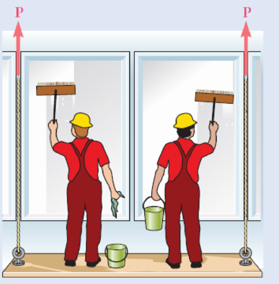
The Load and Resistance Factor Design method is to be used to select the two cables that will raise and lower a platform supporting two window washers. The platform weighs 160 lb and each of the window washers is assumed to weigh 195 lb with equipment. Since these workers are free to move on the platform, 75% of their total weight and the weight of their equipment will be used as the design live load of each cable. (a) Assuming a resistance factor ϕ = 0.85 and load factors γD = 1.2 and γL = 1.5, determine the required minimum ultimate load of one cable. (b) What is the corresponding conventional factor of safety for the selected cables?
Fig. P1.58
Expert Solution & Answer
Want to see the full answer?
Check out a sample textbook solution
Students have asked these similar questions
A load is supported by four 304 stainless steel wires that are connected to the rigid member’s AB and DC. The members were originally horizontal, and each wire has a cross-sectional area of 0.025 in2. When a 500 lb load is applied, the angle of telt is 0.0296° and 0.003405° for the AB and DC members respectively. If the load is reduced to 450 lb but the angles of telt are maintain, what is the temperature change?
A homogeneous 200 kg bar with a length of 6 meters carries a 3 kN force at one end. This bar is supported at the other end by a pin on the wall and the center with 10 mm diameter cable attached to the same wall 4 meters above the pin. What is the tensile load on the cable.
A copper wire of length 1.80 m and diameter 0.80 mm is suspended from two
points, 1.0 m apart and at the same horizontal level. A load of 2.5 kg is hung
from the centre of the wire.
The wire makes an angle 8 to the vertical at point P and experiences a force F
as shown in the diagram below.
THIS DIAGRAM IS NOT SHOWN TO SCALE
i.
0.9 m
ii.
0.5 m
F
Ꮎ : Ꮎ
0.5 m
F
0.9 m
Calculate the angle with which each part of the wire makes with the
vertical at the point where the load is hung.
Determine the stress in the wire.
iii. Determine the strain in the wire.
m = 2.5 kg
(Young's modulus for copper = 1.17 x 10¹¹ Pa)
iv. Determine the extension produced in the wire by this strain.
Chapter 1 Solutions
Mechanics of Materials, 7th Edition
Ch. 1.2 - Two solid cylindrical rods AB and BC are welded...Ch. 1.2 - Two solid cylindrical rods AB and BC are welded...Ch. 1.2 - Two solid cylindrical rods AB and BC are welded...Ch. 1.2 - Two solid cylindrical rods AB and BC are welded...Ch. 1.2 - A strain gage located at C on the surface of bone...Ch. 1.2 - Two brass rods AB and BC, each of uniform...Ch. 1.2 - Each of the four vertical links has an 8 36-mm...Ch. 1.2 - Link AC has a uniform rectangular cross section 18...Ch. 1.2 - Three forces, each of magnitude P = 4 kN, are...Ch. 1.2 - Link BD consists of a single bar 1 in. wide and 12...
Ch. 1.2 - For the Pratt bridge truss and loading shown,...Ch. 1.2 - The frame shown consists of four wooden members,...Ch. 1.2 - An aircraft tow bar is positioned by means of a...Ch. 1.2 - Two hydraulic cylinders are used to control the...Ch. 1.2 - Determine the diameter of the largest circular...Ch. 1.2 - Two wooden planks, each 12 in. thick and 9 in....Ch. 1.2 - When the force P reached 1600 lb, the wooden...Ch. 1.2 - A load P is applied to a steel rod supported as...Ch. 1.2 - The axial force in the column supporting the...Ch. 1.2 - Three wooden planks are fastened together by a...Ch. 1.2 - A 40-kN axial load is applied to a short wooden...Ch. 1.2 - An axial load P is supported by a short W8 40...Ch. 1.2 - Link AB, of width b = 2 in. and thickness t=14...Ch. 1.2 - Determine the largest load P that can be applied...Ch. 1.2 - Knowing that = 40 and P = 9 kN, determine (a) the...Ch. 1.2 - The hydraulic cylinder CF, which partially...Ch. 1.2 - For the assembly and loading of Prob. 1.7,...Ch. 1.2 - Two identical linkage-and-hydraulic-cylinder...Ch. 1.5 - Two wooden members of uniform rectangular cross...Ch. 1.5 - Two wooden members of uniform rectangular cross...Ch. 1.5 - The 1.4-kip load P is supported by two wooden...Ch. 1.5 - Two wooden members of uniform cross section are...Ch. 1.5 - A centric load P is applied to the granite block...Ch. 1.5 - A 240-kip load P is applied to the granite block...Ch. 1.5 - A steel pipe of 400-mm outer diameter is...Ch. 1.5 - A steel pipe of 400-mm outer diameter is...Ch. 1.5 - A steel loop ABCD of length 5 ft and of 38-in....Ch. 1.5 - Link BC is 6 mm thick, has a width w = 25 mm, and...Ch. 1.5 - Link BC is 6 mm thick and is made of a steel with...Ch. 1.5 - Members AB and BC of the truss shown are made of...Ch. 1.5 - Members AB and BC of the truss shown are made of...Ch. 1.5 - Link AB is to be made of a steel for which the...Ch. 1.5 - Two wooden members are joined by plywood splice...Ch. 1.5 - For the joint and loading of Prob. 1.43, determine...Ch. 1.5 - Three 34-in.-diameter steel bolts are to be used...Ch. 1.5 - Three steel bolts are to be used to attach the...Ch. 1.5 - A load P is supported as shown by a steel pin that...Ch. 1.5 - A load P is supported as shown by a steel pin that...Ch. 1.5 - A steel plate 14 in. thick is embedded in a...Ch. 1.5 - Determine the factor of safety for the cable...Ch. 1.5 - Link AC is made of a steel with a 65-ksi ultimate...Ch. 1.5 - Solve Prob. 1.51, assuming that the structure has...Ch. 1.5 - Each of the two vertical links CF connecting the...Ch. 1.5 - Solve Prob. 1.53, assuming that the pins at C and...Ch. 1.5 - In the structure shown, an 8-mm-diameter pin is...Ch. 1.5 - In an alternative design for the structure of...Ch. 1.5 - Prob. 57PCh. 1.5 - The Load and Resistance Factor Design method is to...Ch. 1 - In the marine crane shown, link CD is known to...Ch. 1 - Two horizontal 5-kip forces are applied to pin B...Ch. 1 - For the assembly and loading of Prob. 1.60,...Ch. 1 - Two steel plates are to be held together by means...Ch. 1 - A couple M of magnitude 1500 N m is applied to...Ch. 1 - Knowing that link DE is 18 in. thick and 1 in....Ch. 1 - A 58-in.-diameter steel rod AB is fitted to a...Ch. 1 - In the steel structure shown, a 6-mm-diameter pin...Ch. 1 - Prob. 67RPCh. 1 - A force P is applied as shown to a steel...Ch. 1 - The two portions of member AB are glued together...Ch. 1 - The two portions of member AB are glued together...
Knowledge Booster


Learn more about
Need a deep-dive on the concept behind this application? Look no further. Learn more about this topic, mechanical-engineering and related others by exploring similar questions and additional content below.Similar questions
- Determine the width and thickness of the leaves (in mm) of a leaf spring using the following specifications: Total load = 140 kN; Number of springs supporting the load = 4; Maximum number of leaves = 10; Span of the spring = 1000 mm; Permissible deflection = 80 mm; Modulus of elasticity, E = 200 kN/mm2; and allowable stress in spring material is 600 MPa.arrow_forwardTwo plates of which (2.5 d) and d as outer and inner diameter respectively and thickness 25 mm each are held together by means of a bolt. The bolt material S-400 N/mm² and E210000 N/mm² while plate material E= 72000 N/mm². The initial preload in the bold is 6.0 KN and force on the joint is 12 kN. Find out size of bolt assuming factor of safety 2.0.arrow_forward(13%) Problem 5: A shop sign weighing m;g hangs from one end of a uniform beam weighing mpg. A hinge attaches the other end of the beam to a wall. The beam has a length of l1. A cable is attached to the beam a distance l2 from the hinge to help support the beam. The cable makes an angle 0 with the beam as shown. e 4 Paul's o o. Auto Repair E A 13% Part (a) On the following free body diagram, draw all of the forces acting on the beam, representing the forces as vectors. Use a coordinate systen with the x-axis on the horizontal (along the length of the beam) and the y-axis vertical (perpendicular to the beam). Use "wb" for the weight of the beam, "ws" for the weight of the sign, "FT" for the force of tension, and "H" for the force on the hinge. Finally, since we don't know the angle that the force on the hinge will act based on the diagram alone, let it be acting at an angle be denoted "o" from the positive y-axis. I A 13% Part (b) Using the free body diagram from part (a), write an…arrow_forward
- Two steel pipes are used to support a 50KN load, as shown below. The pipes are connected to the wall (at points A and C) and each other (at point B) with pin joints. The load is applied at point B. a. Draw free body diagrams for the two pipes and the pin joint at point B. b. Find the support forces at the wall at points A and C. 1.25m A 50KN 1.15marrow_forwardThe inner spring of a compound helical spring is arranged within and concentric with the outer one and is shorter by 9 mm. The outer spring has 10 coils with a mean diameter of 24 mm and a wire diameter of 3 mm. (a) Determine the stiffness of the inner spring when an axial load of 162 N causes the outer spring to compress by 16 mm. If the radial clearance between the springs is 1.5 mm and the inner spring has 8 coils, find its wire diameter. (c) Disregarding the effect of curvature, find the maximum shear stress in each of the spring. Given G = 78 GPa.arrow_forwardQ1. A simply supported pedestrian bridge is to be constructed in a city park and two designs have been proposed as shown in Figure 1, case a and case b, respectively. The truss members are to be made from timber. The dead load and live load transmitted to the bottom joints of the truss are 147.25 N/m and 4500 N/m, respectively. In each case find the member subjected to the largest tension and largest compression load and suggest why you would choose one design over the other. Neglect the weights of the truss members. 1.25 m 1.25 m -1.25 m -- 1.25 m 1.25 m- case a 1.25 m F1. -1.25 m1.25 m- case b Figure 1arrow_forward
- To calculate the maximum axial loads for a column based on yielding and buckling about both axes, and allowing for factors of safety. The critical load P for buckling of a column depends on the vertical distance between supports and how the column is connected to those supports. The length L in the T'EI formula Per =- is the distance between points of zero moment. For a pin- L2 supported column, this is the full height of the column. For a column that is not pinned at both ends, the points of zero moment are not at the supports. The equation for the critical load can be modified to use an effective length Le = KL, where K depends on the support conditions. For a column fixed at both ends, K = 0.5. For a column fixed at one end and pinned at the other, K = 0.7 (Figure 1). The equation for the critical load then becomes ’EI Pa (KL)²arrow_forwardA steel cable with a diameter of 3.0cm supports a load of 2.0 kN. What is the frictional length increase of the cable compared with the length when there is no load if Y= 200 GPa?arrow_forwardThe figure gives the cross-section of a grade 25 cast-iron pressure vessel. A total of N bolts are to be used to resist a separating force of 150 kN. (a) Determine kb, km, and C. (b) Find the number of bolts required for a load factor of 2 where the bolts may be reused when the joint is taken apart. (c) With the number of bolts obtained in part (b), determine the realized load factor for overload, the yielding factor of safety, and the load factor for joint separation. Use (SI) units as it appliesarrow_forward
- Figure 5.5 t - 16.0 411 A If the tension developed in cables AB and AC cannot exceed 460 lb, determine the largest weight of the crate that can be supported. (Figure 1) k Express your answer to three significant figures and include the appropriate units. Wmax= Submit ▼ Part B μÅ Value Request Answer μA 4 Units Also, what is the force developed along strut AD? Express your answer to three significant figures and include the appropriate units. P Pearson FERME ? DMC ? Copyright © 2023 Pearson Education Inc. All rights reserved. | Terms of Use | Privacy Policy | Permissions | Contact Us | Review 46°F Cloudy ^ 11:15 PM (4) 4/19/2023arrow_forwardProblem 1: Three vertical posts AD, BE, and CF are held between two horizontal rigid plates. Posts AD and CF are made of steel (Es = 200 GPa) and have cross sectional areas of 1000 mm² each. Post BE is made of aluminum (Ea = 73.1 GPa) and has a cross sectional area of 1500 mm². Initially, there is a small gap of 0.1 mm between BE and the top horizontal plate. Then a vertical force of P = 410 kN is applied, which is more than sufficient to close the gap completely. D -0.5 m B E -0.5 m- 0.4 m F Determine the normal stresses in posts AD, BE, and CF (both magnitude and sign).arrow_forwardThe following data is referring to a screw jack. The vertical load on the screw = 20kN Force applied at the lever end whose length = 80cm The mean radius of the screw = 2.5cm Pitch of the screw =1cm Co-efficient of friction between the screw thread and the nut = 0.15 Determine the force on the lever end while raising the load and efficiency of the screw jackarrow_forward
arrow_back_ios
SEE MORE QUESTIONS
arrow_forward_ios
Recommended textbooks for you
 Elements Of ElectromagneticsMechanical EngineeringISBN:9780190698614Author:Sadiku, Matthew N. O.Publisher:Oxford University Press
 Mechanics of Materials (10th Edition)Mechanical EngineeringISBN:9780134319650Author:Russell C. HibbelerPublisher:PEARSON
 Thermodynamics: An Engineering ApproachMechanical EngineeringISBN:9781259822674Author:Yunus A. Cengel Dr., Michael A. BolesPublisher:McGraw-Hill Education
 Control Systems EngineeringMechanical EngineeringISBN:9781118170519Author:Norman S. NisePublisher:WILEY
 Mechanics of Materials (MindTap Course List)Mechanical EngineeringISBN:9781337093347Author:Barry J. Goodno, James M. GerePublisher:Cengage Learning
 Engineering Mechanics: StaticsMechanical EngineeringISBN:9781118807330Author:James L. Meriam, L. G. Kraige, J. N. BoltonPublisher:WILEY
Elements Of Electromagnetics
Mechanical Engineering
ISBN:9780190698614
Author:Sadiku, Matthew N. O.
Publisher:Oxford University Press
Mechanics of Materials (10th Edition)
Mechanical Engineering
ISBN:9780134319650
Author:Russell C. Hibbeler
Publisher:PEARSON
Thermodynamics: An Engineering Approach
Mechanical Engineering
ISBN:9781259822674
Author:Yunus A. Cengel Dr., Michael A. Boles
Publisher:McGraw-Hill Education
Control Systems Engineering
Mechanical Engineering
ISBN:9781118170519
Author:Norman S. Nise
Publisher:WILEY
Mechanics of Materials (MindTap Course List)
Mechanical Engineering
ISBN:9781337093347
Author:Barry J. Goodno, James M. Gere
Publisher:Cengage Learning
Engineering Mechanics: Statics
Mechanical Engineering
ISBN:9781118807330
Author:James L. Meriam, L. G. Kraige, J. N. Bolton
Publisher:WILEY
Ch 2 - 2.2.2 Forced Undamped Oscillation; Author: Benjamin Drew;https://www.youtube.com/watch?v=6Tb7Rx-bCWE;License: Standard youtube license