
Mechanics of Materials, 7th Edition
7th Edition
ISBN: 9780073398235
Author: Ferdinand P. Beer, E. Russell Johnston Jr., John T. DeWolf, David F. Mazurek
Publisher: McGraw-Hill Education
expand_more
expand_more
format_list_bulleted
Videos
Textbook Question
Chapter 1.2, Problem 19P
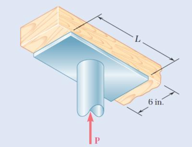
The axial force in the column supporting the timber beam shown is P = 20 kips. Determine the smallest allowable length L of the bearing plate if the bearing stress in the timber is not to exceed 400 psi.
Fig. P1.19
Expert Solution & Answer
Want to see the full answer?
Check out a sample textbook solution
Students have asked these similar questions
Straight rods of 0.30-in. diameter and 200-ft length are sometimes used to clear underground conduits of obstructions or to thread wires through a new conduit. The rods are made of high-strength steel and, for storage and transportation, are wrapped on spools of 5-ft diameter. Assuming that the yield strength is not exceeded, determine (a) the maximum stress in a rod, when the rod, which was initially straight, is wrapped on the spool, (b) the corresponding bending moment in the rod. Use E= 29 * 106 psi.
Two forces P can be applied separately or at the same time to a plate that is welded to a solid circular bar of radius r. Determine the largest compressive stress in the circular bar (a) when both forces are applied, (b) when only one of the forces is applied.
The five-bolt connection shown must support an applied load of P = 330 kN. If the average shear stress in the bolts must be limited to 295 MPa, determine the minimum bolt diameter that may be used in the connection.
Chapter 1 Solutions
Mechanics of Materials, 7th Edition
Ch. 1.2 - Two solid cylindrical rods AB and BC are welded...Ch. 1.2 - Two solid cylindrical rods AB and BC are welded...Ch. 1.2 - Two solid cylindrical rods AB and BC are welded...Ch. 1.2 - Two solid cylindrical rods AB and BC are welded...Ch. 1.2 - A strain gage located at C on the surface of bone...Ch. 1.2 - Two brass rods AB and BC, each of uniform...Ch. 1.2 - Each of the four vertical links has an 8 36-mm...Ch. 1.2 - Link AC has a uniform rectangular cross section 18...Ch. 1.2 - Three forces, each of magnitude P = 4 kN, are...Ch. 1.2 - Link BD consists of a single bar 1 in. wide and 12...
Ch. 1.2 - For the Pratt bridge truss and loading shown,...Ch. 1.2 - The frame shown consists of four wooden members,...Ch. 1.2 - An aircraft tow bar is positioned by means of a...Ch. 1.2 - Two hydraulic cylinders are used to control the...Ch. 1.2 - Determine the diameter of the largest circular...Ch. 1.2 - Two wooden planks, each 12 in. thick and 9 in....Ch. 1.2 - When the force P reached 1600 lb, the wooden...Ch. 1.2 - A load P is applied to a steel rod supported as...Ch. 1.2 - The axial force in the column supporting the...Ch. 1.2 - Three wooden planks are fastened together by a...Ch. 1.2 - A 40-kN axial load is applied to a short wooden...Ch. 1.2 - An axial load P is supported by a short W8 40...Ch. 1.2 - Link AB, of width b = 2 in. and thickness t=14...Ch. 1.2 - Determine the largest load P that can be applied...Ch. 1.2 - Knowing that = 40 and P = 9 kN, determine (a) the...Ch. 1.2 - The hydraulic cylinder CF, which partially...Ch. 1.2 - For the assembly and loading of Prob. 1.7,...Ch. 1.2 - Two identical linkage-and-hydraulic-cylinder...Ch. 1.5 - Two wooden members of uniform rectangular cross...Ch. 1.5 - Two wooden members of uniform rectangular cross...Ch. 1.5 - The 1.4-kip load P is supported by two wooden...Ch. 1.5 - Two wooden members of uniform cross section are...Ch. 1.5 - A centric load P is applied to the granite block...Ch. 1.5 - A 240-kip load P is applied to the granite block...Ch. 1.5 - A steel pipe of 400-mm outer diameter is...Ch. 1.5 - A steel pipe of 400-mm outer diameter is...Ch. 1.5 - A steel loop ABCD of length 5 ft and of 38-in....Ch. 1.5 - Link BC is 6 mm thick, has a width w = 25 mm, and...Ch. 1.5 - Link BC is 6 mm thick and is made of a steel with...Ch. 1.5 - Members AB and BC of the truss shown are made of...Ch. 1.5 - Members AB and BC of the truss shown are made of...Ch. 1.5 - Link AB is to be made of a steel for which the...Ch. 1.5 - Two wooden members are joined by plywood splice...Ch. 1.5 - For the joint and loading of Prob. 1.43, determine...Ch. 1.5 - Three 34-in.-diameter steel bolts are to be used...Ch. 1.5 - Three steel bolts are to be used to attach the...Ch. 1.5 - A load P is supported as shown by a steel pin that...Ch. 1.5 - A load P is supported as shown by a steel pin that...Ch. 1.5 - A steel plate 14 in. thick is embedded in a...Ch. 1.5 - Determine the factor of safety for the cable...Ch. 1.5 - Link AC is made of a steel with a 65-ksi ultimate...Ch. 1.5 - Solve Prob. 1.51, assuming that the structure has...Ch. 1.5 - Each of the two vertical links CF connecting the...Ch. 1.5 - Solve Prob. 1.53, assuming that the pins at C and...Ch. 1.5 - In the structure shown, an 8-mm-diameter pin is...Ch. 1.5 - In an alternative design for the structure of...Ch. 1.5 - Prob. 57PCh. 1.5 - The Load and Resistance Factor Design method is to...Ch. 1 - In the marine crane shown, link CD is known to...Ch. 1 - Two horizontal 5-kip forces are applied to pin B...Ch. 1 - For the assembly and loading of Prob. 1.60,...Ch. 1 - Two steel plates are to be held together by means...Ch. 1 - A couple M of magnitude 1500 N m is applied to...Ch. 1 - Knowing that link DE is 18 in. thick and 1 in....Ch. 1 - A 58-in.-diameter steel rod AB is fitted to a...Ch. 1 - In the steel structure shown, a 6-mm-diameter pin...Ch. 1 - Prob. 67RPCh. 1 - A force P is applied as shown to a steel...Ch. 1 - The two portions of member AB are glued together...Ch. 1 - The two portions of member AB are glued together...
Knowledge Booster


Learn more about
Need a deep-dive on the concept behind this application? Look no further. Learn more about this topic, mechanical-engineering and related others by exploring similar questions and additional content below.Similar questions
- Two cylindrical rods, one of steel and the other of brass, are joined at C and restrained by rigid supports at A and E. The steel rod has a length of 300 mm while the brass rod has a length of 200 mm. The diameters of the rods are shown in the figure below. A force of 60 kN is applied at point B of the steel segment. For the loading shown and knowing that modulus of elasticity values for steel and brass are respectively Es = 200 GPa and Eb = 105 GPa, determine a.) The reactions at A and E: RA and RE. b.) The deflection of point C from its original location. how to doarrow_forwardKnowing that connecting rod BD has a uniform cross section of area equal to 800 mm², determine the magnitude of the load P so that the normal stress in rod BD is 50 MPa.arrow_forwardA timber beam AB of length L and rectangular cross section carries a single concentrated load P at its midpoint C. (a) Show that the ratio Tm/ m of the maximum values of the shearing and normal stresses in the beam is equal to h/2L, where h and L are, respectively, the depth and the length of the beam. (b) Determine the depth h and the width b of the beam, knowing that L = 2 m, P = 40 kN, 7m = 960 kPa, and om = 12 MPa.arrow_forward
- Determine the values of the stress in portions AC and CB of the steel bar shown Fig. when the temperature of the bar is 2508F, knowing that a close fit exists at both of the rigid supports when the temperature is 1758F. Use the values E=29 *106 psi and α=6.5 * 10–6/8F for steelarrow_forwardA glue-laminated column of 3-m effective length is to be made from boards of 24 x 100-mm cross section. Knowing that for the grade of wood used, E= 11 GPa and the adjusted allowable stress for com-pression parallel to the grain is σC= 9 MPa, determine the number of boards that must be used to support the centric load shown when (a) P= 34 kN, (b) P= 17 kNarrow_forwardA 40-kN axial load is applied to a short wooden post that is supported by a concrete footing resting on undisturbed soil. Determine (a) the maximum bearing stress on the concrete footing, (b) the size of the footing for which the average bearing stress in the soil is 145 kPa.arrow_forward
- A horizontal shelf AD of length L=1215mm, width b=305mm, and thickness t=22mm is supported by brackets B and C (Fig A). Note that the shelf is symmetric: AB=CD. The brackets are adjustable and may be placed in any desired positions between the ends of the shelf. A uniform load of intensity q, which includes the weight of the shelf itself, acts on the shelf. determine the maximum permissible value of the load q if the allowable bending stress in the self is = 8.5MPa and the position of the support is adjusted for maximum load-carrying capacity.arrow_forwardThe lap joint shown is connected by three 16-mm diameter rivets. If the allowable stress for shear in rivets is 40 MPa and bearing between therivets and the plates is 60 MPa determine the safe load P.arrow_forwardDetermine the largest axial load P that can be safely supported by a flat steel bar consisting of two portions, both 10 mm thick and, respectively, 40 and 80 mm wide, connected by fillets of radius r=4 mm. Assume an allowable normal stress of 180 MPa.arrow_forward
- The outside diameter of the steel pipe shown is 220 mm and its wall thickness is 6.0 mm. The upper bearing plate has the same width as the reinforced concrete beam it supports. The total load on the column by the reinforced concrete beam is 550 kN. Determine: A. The length L of the rectangular upper bearing plate if its width is 275 mm. and the average bearing stress between the steel plate and the reinforced concrete beam is not to exceed 6.2 MPa.arrow_forwardA compressive member of a structure is of 25 mm square cross-section and carries a load of 50 kN. Determine, from first principles, the normal, tangential, and resultant stresses on a plane inclined at 60° to the axis of the bar.arrow_forwardFor the connection shown, the average shear stress in the 16-mm-diameter bolts must be limited to 270 MPa. Determine the maximum load P that may be applied to the connection.arrow_forward
arrow_back_ios
SEE MORE QUESTIONS
arrow_forward_ios
Recommended textbooks for you
 Elements Of ElectromagneticsMechanical EngineeringISBN:9780190698614Author:Sadiku, Matthew N. O.Publisher:Oxford University Press
 Mechanics of Materials (10th Edition)Mechanical EngineeringISBN:9780134319650Author:Russell C. HibbelerPublisher:PEARSON
 Thermodynamics: An Engineering ApproachMechanical EngineeringISBN:9781259822674Author:Yunus A. Cengel Dr., Michael A. BolesPublisher:McGraw-Hill Education
 Control Systems EngineeringMechanical EngineeringISBN:9781118170519Author:Norman S. NisePublisher:WILEY
 Mechanics of Materials (MindTap Course List)Mechanical EngineeringISBN:9781337093347Author:Barry J. Goodno, James M. GerePublisher:Cengage Learning
 Engineering Mechanics: StaticsMechanical EngineeringISBN:9781118807330Author:James L. Meriam, L. G. Kraige, J. N. BoltonPublisher:WILEY
Elements Of Electromagnetics
Mechanical Engineering
ISBN:9780190698614
Author:Sadiku, Matthew N. O.
Publisher:Oxford University Press
Mechanics of Materials (10th Edition)
Mechanical Engineering
ISBN:9780134319650
Author:Russell C. Hibbeler
Publisher:PEARSON
Thermodynamics: An Engineering Approach
Mechanical Engineering
ISBN:9781259822674
Author:Yunus A. Cengel Dr., Michael A. Boles
Publisher:McGraw-Hill Education
Control Systems Engineering
Mechanical Engineering
ISBN:9781118170519
Author:Norman S. Nise
Publisher:WILEY
Mechanics of Materials (MindTap Course List)
Mechanical Engineering
ISBN:9781337093347
Author:Barry J. Goodno, James M. Gere
Publisher:Cengage Learning
Engineering Mechanics: Statics
Mechanical Engineering
ISBN:9781118807330
Author:James L. Meriam, L. G. Kraige, J. N. Bolton
Publisher:WILEY
An Introduction to Stress and Strain; Author: The Efficient Engineer;https://www.youtube.com/watch?v=aQf6Q8t1FQE;License: Standard YouTube License, CC-BY