
Videos
- (a) For the circuit in Fig. 14.97, draw the new circuit after it has been scaled by Km = 200 and Kf = 104.
- (b) Obtain the Thevenin equivalent impedance at terminals a-b of the scaled circuit at ω = 104 rad/s.
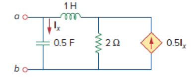
Figure 14.97
(a)
Draw the new circuit for the circuit in Figure 14.97 after it has been magnitude scaled by a factor of
Explanation of Solution
Given data:
Refer to Figure 14.97 in the textbook.
The value of the magnitude scaling factor
The value of the frequency scaling factor
Formula used:
Consider the equations used in magnitude and frequency scaling.
Write the expression to calculate the scaled resistor.
Here,
Write the expression to calculate the scaled inductor.
Here,
Write the expression to calculate the scaled capacitor.
Here,
Calculation:
The given circuit is redrawn as Figure 1.
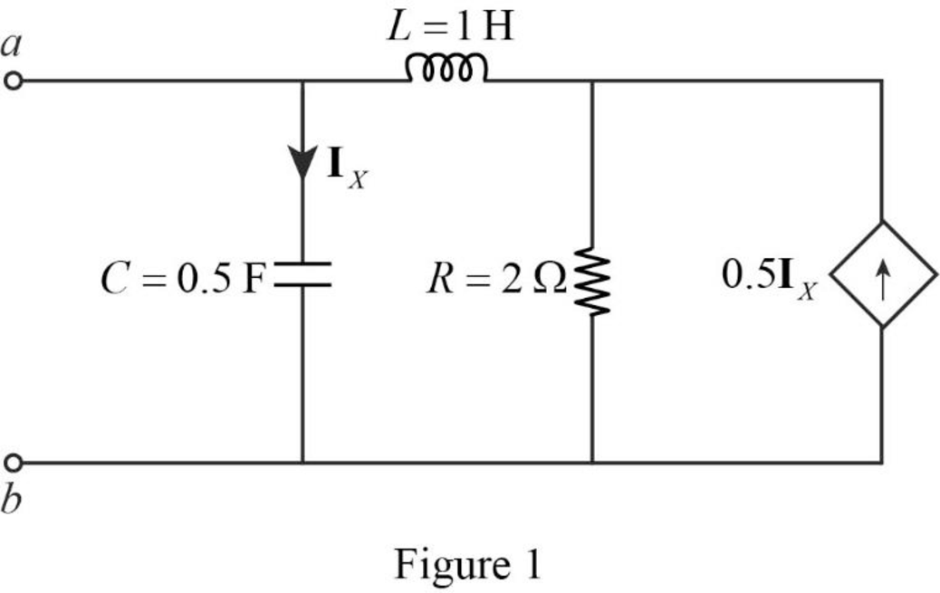
Refer to Figure 1, the value of the resistor
Substitute
Substitute
Substitute
The redesigned circuit is drawn as Figure 2 which is obtained by using the magnitude and frequency scaling on the circuit in Figure 1.
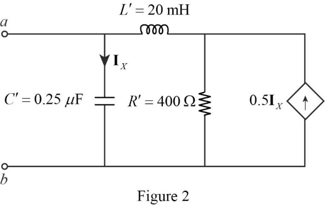
Conclusion:
Thus, the new circuit for the circuit in Figure 14.97 is drawn by using the magnitude and frequency scaling.
(b)
Find the value of the Thevenin equivalent impedance at terminals a-b of the scaled circuit.
Answer to Problem 80P
The value of the Thevenin equivalent impedance
Explanation of Solution
Given data:
The value of the angular frequency
Formula used:
Write the expression to calculate the impedance of the passive elements resistor, inductor and capacitor in s-domain.
Here,
Calculation:
Use equation (4) to find
Use equation (5) to find
Use equation (6) to find
Insert a
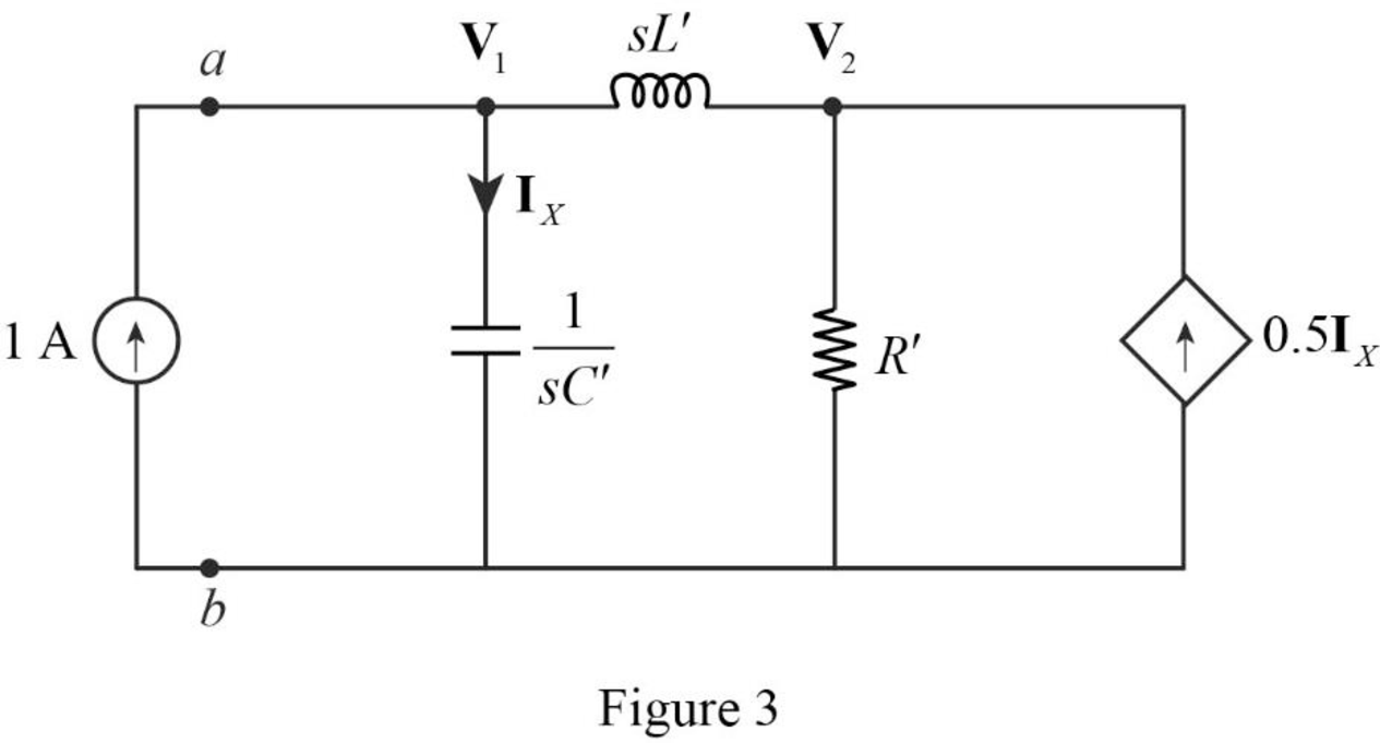
Apply Kirchhoff’s current law on Figure 3 to find
Rearrange the above equation.
Apply Kirchhoff’s current law on Figure 3 to find
Refer to Figure 3, the current
Substitute
By comparing the equations (7) and (9), the following equation is obtained.
Rearrange the above equation to find
Substitute
Simplify the above equation.
Simplify the above equation to find
Refer to Figure 3, the Thevenin equivalent impedance across the a-b terminals are calculated as follows.
Substitute
Substitute
Substitute
Simplify the above equation to find
Conclusion:
Thus, the value of the Thevenin equivalent impedance
Want to see more full solutions like this?
Chapter 14 Solutions
Fundamentals of Electric Circuits


- 388 / 5000 Çeviri sonuçları In the circuit in the figure, Rs = 3.8 kΩ, R1 = 82 kΩ, R2 = 22 kΩ, RC = 5.6 kΩ, RE = 1.5 kΩ and RL = 3.3 kΩ and β = 150.Since the capacitances are C1 = 0.5 μF and C2 = 0.53 μF, what is the low cutoff frequency of the given circuit? NOTE-1: In the middle band frequency, β = 150 will be taken and the frequency dependence of β will not be taken into account. NOTE-2: The output impedance of the transistor r0 will be neglected in the calculations.arrow_forwardAn AC series circuit has a resistance of 10 ohms, and inductance of 0.2 H, and a capacitance of 60 micro Farad. Calculate: (a) the resonant frequency, (b) thecurrent, and (c) the power at resonance. Given that the applied voltage is 200 V. draw the circuit diagramarrow_forwardWhat is the impedance of a circuit containing a 32002 resistor, 0.1H inductor, and 6.2 µF capacitor in series? Show in rectangular and polar form. Assume frequency is 60Hz.arrow_forward
- Electronic In the circuit in the figure, Rs = 3.8 kΩ, R1 = 82 kΩ, R2 = 22 kΩ, RC = 5.6 kΩ, RE = 1.5 kΩ and RL = 3.3 kΩ and β = 150. Given that the capacitances are C1 = 0.5 μF and C2 = 0.84 μF, what is the low cutoff frequency of the given circuit? NOTE-1: In the middle band frequency, β = 150 will be taken and the frequency dependence of β will not be taken into account. NOTE-2: The output impedance of the transistor r0 will be neglected in the calculations.arrow_forward2. Given the simple RC circuit below, determine the circuit gain V2(s) / V1(s) in terms of circuit impedance Z(s) = V(s) / I(s) for each of the resistive and capacitive element.arrow_forwardQ.4: Choose the suitable choice for the following sentences. 1. At any resonant circuit the input impedance is ....... a. XL. b. RT. c. XC. 2. The locus of inductive load is a vector in the …... quadrant. a. 4th. b. 2nd. c. 3rd. 3. For non-sinusoidal input signal, the power dissipated in a resistance is equal to ............ a. 2I2R. b. Iav2R. c. Ieff2R. 4. Applying Kirchhoff's laws to RL & RC transient circuits produces Equations of type:a. Time-Depend. b. Time-Variable. c. Differential. 5. The Differential Equations applied RL & RC transient circuits are:a. Third-order b. Second-order c. First-order 6. Electrical energy is stored in ........ a. Inductance. b. Capacitance. c. Both-of-them. 7. .......... is obtained in parallel resonance circuit. a. Vmax. b. Imax. c. Pmax. 8. The total impedance angle is ............ on the frequency of the harmonic.a. Dependent. b. Independent. c. Both-of-them. 9. In transient circuit, the capacitor behaves as ................ when the switch…arrow_forward
- Determine a frequency ω that will cause the input x(t) = cos(ωt) to produce a strong response when applied tothe system descriptbed by (D2 + 2D + 13/4) y(t) = x(t). Carfully explain your choicearrow_forwardIn the circuit in the figure, Rs = 3.8 kΩ, R1 = 82 kΩ, R2 = 22 kΩ, RC = 5.6 kΩ, RE = 1.5 kΩ and RL = 3.3 kΩ and β = 150. Since the capacitances are C1 = 0.5 μF and C2 = 0.21 μF, what is the low cutoff frequency of the given circuit? NOTE-1: In the middle band frequency, β = 150 will be taken and the frequency dependence of β will not be taken into account. NOTE-2: The output impedance of the transistor r0 will be neglected in the calculations. a. 159,27 Hz b. 22,75 Hz c. 68,26 Hz d. 91,01 Hz e. 227,52 Hz f. 113,76 Hz g. 273,03 Hz h. 182,02 Hzarrow_forward1. Calculate the total impedance of the circuits in Fig. Express your answer inrectangular and polar forms. (c) ZT Rectangluar form -> ZT = 5k + 10kj Polar form -> ZT = 11.18kΩ∠63.43° I manage to fix the answer on part C of the first question can you check if my answer in part C is correct?arrow_forward
- In the circuit in the figure, Rs = 3.8 kohm, R₁ = 82 kohm, R₂ = 22 Kohm, Rc = 5.6 Kohm, RE = 1.5 k and R₁ = 3.3 k and B = 150. Since the capacitances are C1 = 0.5 µF and C2 = 0.8 µF, what is the low cutoff frequency of the given circuit? NOTE-1: In the middle band frequency, B = 150 will be taken and frequency dependence of B will not be taken into account. NOTE-2: The output impedance of the transistor will be neglected in ro calculations.arrow_forwardA circuit is designed with an AC source of max voltage 12 and frequency 60 Hz. The circuit has a resistance of 1050 Ohms, an inductance of 0.06 Henrys, and a capacitance of 0.009 coulombs per volt. - omega for source in rad/s? - omegaR for circuit? -XL? -XC? -phi in radians? -Z? -imax?arrow_forwardA LC circuit in a radio tuned to 1080 kHz has an inductor with an inductance value of 60 μH and a resistance of 0.25 Ω. a. what is the capacitance of the LC circuit? b. sketch the impedance phasor diagram for the radio. Be sure to label important features of the diagram.arrow_forward
 Introductory Circuit Analysis (13th Edition)Electrical EngineeringISBN:9780133923605Author:Robert L. BoylestadPublisher:PEARSON
 Delmar's Standard Textbook Of ElectricityElectrical EngineeringISBN:9781337900348Author:Stephen L. HermanPublisher:Cengage Learning
 Programmable Logic ControllersElectrical EngineeringISBN:9780073373843Author:Frank D. PetruzellaPublisher:McGraw-Hill Education
 Fundamentals of Electric CircuitsElectrical EngineeringISBN:9780078028229Author:Charles K Alexander, Matthew SadikuPublisher:McGraw-Hill Education
 Electric Circuits. (11th Edition)Electrical EngineeringISBN:9780134746968Author:James W. Nilsson, Susan RiedelPublisher:PEARSON
 Engineering ElectromagneticsElectrical EngineeringISBN:9780078028151Author:Hayt, William H. (william Hart), Jr, BUCK, John A.Publisher:Mcgraw-hill Education,