
Fundamentals of Electric Circuits
6th Edition
ISBN: 9780078028229
Author: Charles K Alexander, Matthew Sadiku
Publisher: McGraw-Hill Education
expand_more
expand_more
format_list_bulleted
Videos
Textbook Question
Chapter 14, Problem 2P
Using Fig. 14.69, design a problem to help other students better understand how to determine transfer functions.
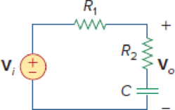
Figure 14.69
Expert Solution & Answer
Want to see the full answer?
Check out a sample textbook solution
Students have asked these similar questions
Design of 2nd-order LPF
The poles of a normalized second-order LPF ([H(w = 0)| = 1) is shown on the complex plane below:
%3D
Infinite seires is a very important topic in signal processing.
Determine the value of the following sequence:
y=1+(1/4)+(1/16)+(1/64)+.....
Nyquist plot
Draw a
Example
GES) =
Nyquist plot
1+ 45
$(+s)(+25)
Chapter 14 Solutions
Fundamentals of Electric Circuits
Ch. 14.2 - Obtain the transfer function VoVs of the RL...Ch. 14.2 - Prob. 2PPCh. 14.4 - Draw the Bode plots for the transfer function...Ch. 14.4 - Sketch the Bode plots for H()=50j(j+4)(j+10)2Ch. 14.4 - Construct the Bode plots for H(s)=10s(s2+80s+400)Ch. 14.4 - Obtain the transfer function H() corresponding to...Ch. 14.5 - A series-connected circuit has R = 4 and L = 25...Ch. 14.6 - A parallel resonant circuit has R = 100 k, L = 50...Ch. 14.6 - Calculate the resonant frequency of the circuit in...Ch. 14.7 - For the circuit in Fig. 14.40, obtain the transfer...
Ch. 14.7 - Design a band-pass filter of the form in Fig....Ch. 14.8 - Design a high-pass filter with a high-frequency...Ch. 14.8 - Design a notch filter based on Fig. 14.47 for 0 =...Ch. 14.9 - Prob. 14PPCh. 14.10 - Obtain the frequency response of the circuit in...Ch. 14.10 - Consider the network in Fig. 14.57. Use PSpice to...Ch. 14.12 - For an FM radio receiver, the incoming wave is in...Ch. 14.12 - Repeat Example 14.18 for band-pass filter BP6....Ch. 14.12 - If each speaker in Fig. 14.66 has an 8- resistance...Ch. 14 - Prob. 1RQCh. 14 - On the Bode magnitude plot, the slope of 1/5+j2...Ch. 14 - On the Bode phase plot for 0.5 50, the slope of...Ch. 14 - How much inductance is needed to resonate at 5 kHz...Ch. 14 - The difference between the half-power frequencies...Ch. 14 - Prob. 6RQCh. 14 - Prob. 7RQCh. 14 - Prob. 8RQCh. 14 - What kind of filter can be used to select a signal...Ch. 14 - A voltage source supplies a signal of constant...Ch. 14 - Find the transfer function Io/Ii of the RL circuit...Ch. 14 - Using Fig. 14.69, design a problem to help other...Ch. 14 - For the circuit shown in Fig. 14.70, find H(s) =...Ch. 14 - Find the transfer function H(s) = Vo/Vi of the...Ch. 14 - For the circuit shown in Fig. 14.72, find H(s) =...Ch. 14 - For the circuit shown in Fig. 14.73, find H(s) =...Ch. 14 - Calculate |H()| if HdB equals (a) 0.1 dB (b) 5 dB...Ch. 14 - Design a problem to help other students calculate...Ch. 14 - A ladder network has a voltage gain of...Ch. 14 - Design a problem to help other students better...Ch. 14 - Sketch the Bode plots for H()=0.2(10+j)j(2+j)Ch. 14 - A transfer function is given by...Ch. 14 - Construct the Bode plots for...Ch. 14 - Draw the Bode plots for H()=250(j+1)j(2+10j+25)Ch. 14 - Prob. 15PCh. 14 - Sketch Bode magnitude and phase plots for...Ch. 14 - Sketch the Bode plots for G(s)=s(s+2)2(s+1), s = jCh. 14 - A linear network has this transfer function...Ch. 14 - Sketch the asymptotic Bode plots of the magnitude...Ch. 14 - Design a more complex problem than given in Prob....Ch. 14 - Sketch the magnitude Bode plot for...Ch. 14 - Find the transfer function H() with the Bode...Ch. 14 - The Bode magnitude plot of H() is shown in Fig....Ch. 14 - The magnitude plot in Fig. 14.76 represents the...Ch. 14 - A series RLC network has R = 2 k, L = 40 mH, and C...Ch. 14 - Design a problem to help other students better...Ch. 14 - Design a series RLC resonant circuit with 0 = 40...Ch. 14 - Design a series RLC circuit with B = 20 rad/s and...Ch. 14 - Let vs = 20 cos(at) V in the circuit of Fig....Ch. 14 - A circuit consisting of a coil with inductance 10...Ch. 14 - Design a parallel resonant RLC circuit with 0 =...Ch. 14 - Design a problem to help other students better...Ch. 14 - A parallel resonant circuit with a bandwidth of 40...Ch. 14 - A parallel RLC circuit has R = 100 k, L = 100 mH,...Ch. 14 - A parallel RLC circuit has R = 10 k, L = 100 mH,...Ch. 14 - It is expected that a parallel RLC resonant...Ch. 14 - Rework Prob. 14.25 if the elements are connected...Ch. 14 - Find the resonant frequency of the circuit in Fig....Ch. 14 - For the tank circuit in Fig. 14.79, find the...Ch. 14 - Prob. 40PCh. 14 - Using Fig. 14.80, design a problem to help other...Ch. 14 - For the circuits in Fig. 14.81, find the resonant...Ch. 14 - Calculate the resonant frequency of each of the...Ch. 14 - For the circuit in Fig. 14.83, find: (a) the...Ch. 14 - For the circuit shown in Fig. 14.84. find 0, B,...Ch. 14 - For the network illustrated in Fig. 14.85, find...Ch. 14 - Prob. 47PCh. 14 - Find the transfer function Vo/Vs of the circuit in...Ch. 14 - Design a problem to help other students better...Ch. 14 - Determine what type of filter is in Fig. 14.87....Ch. 14 - Design an RL low-pass filter that uses a 40-mH...Ch. 14 - Design a problem to help other students better...Ch. 14 - Design a series RLC type band-pass filter with...Ch. 14 - Design a passive band-stop filter with 0 = 10...Ch. 14 - Determine the range of frequencies that will be...Ch. 14 - (a) Show that for a band-pass filter,...Ch. 14 - Determine the center frequency and bandwidth of...Ch. 14 - The circuit parameters for a series RLC band-stop...Ch. 14 - Find the bandwidth and center frequency of the...Ch. 14 - Obtain the transfer function of a high-pass filter...Ch. 14 - Find the transfer function for each of the active...Ch. 14 - The filter in Fig. 14.90(b) has a 3-dB cutoff...Ch. 14 - Design an active first-order high-pass filter with...Ch. 14 - Obtain the transfer function of the active filter...Ch. 14 - A high-pass filter is shown in Fig. 14.92. Show...Ch. 14 - A general first-order filter is shown in Fig....Ch. 14 - Design an active low-pass filter with dc gain of...Ch. 14 - Design a problem to help other students better...Ch. 14 - Design the filter in Fig. 14.94 to meet the...Ch. 14 - A second-order active filter known as a...Ch. 14 - Use magnitude and frequency scaling on the circuit...Ch. 14 - Design a problem to help other students better...Ch. 14 - Calculate the values of R, L, and C that will...Ch. 14 - Prob. 74PCh. 14 - In an RLC circuit, R = 20 , L = 4 H, and C = 1 F....Ch. 14 - Given a parallel RLC circuit with R = 5 k, L = 10...Ch. 14 - A series RLC circuit has R = 10 , 0 = 40 rad/s,...Ch. 14 - Redesign the circuit in Fig. 14.85 so that all...Ch. 14 - Refer to the network in Fig. 14.96. (a) Find...Ch. 14 - (a) For the circuit in Fig. 14.97, draw the new...Ch. 14 - The circuit shown in Fig. 14.98 has the impedance...Ch. 14 - Scale the low-pass active filter in Fig. 14.99 so...Ch. 14 - The op amp circuit in Fig. 14.100 is to be...Ch. 14 - Using PSpice or MultiSim, obtain the frequency...Ch. 14 - Use PSpice or MultiSim to obtain the magnitude and...Ch. 14 - Using Fig. 14.103, design a problem to help other...Ch. 14 - In the interval 0.1 f 100 Hz, plot the response...Ch. 14 - Use PSpice or MultiSim to generate the magnitude...Ch. 14 - Obtain the magnitude plot of the response Vo in...Ch. 14 - Obtain the frequency response of the circuit in...Ch. 14 - For the tank circuit of Fig. 14.79, obtain the...Ch. 14 - Using PSpice or MultiSim, plot the magnitude of...Ch. 14 - For the phase shifter circuit shown in Fig....Ch. 14 - For an emergency situation, an engineer needs to...Ch. 14 - A series-tuned antenna circuit consists of a...Ch. 14 - The crossover circuit in Fig. 14.108 is a low-pass...Ch. 14 - The crossover circuit in Fig. 14.109 is a...Ch. 14 - A certain electronic test circuit produced a...Ch. 14 - In an electronic device, a series circuit is...Ch. 14 - In a certain application, a simple RC low-pass...Ch. 14 - In an amplifier circuit, a simple RC high-pass...Ch. 14 - Practical RC filter design should allow for source...Ch. 14 - The RC circuit in Fig. 14.111 is used for a lead...Ch. 14 - A low-quality-factor, double-tuned band-pass...
Knowledge Booster


Learn more about
Need a deep-dive on the concept behind this application? Look no further. Learn more about this topic, electrical-engineering and related others by exploring similar questions and additional content below.Similar questions
- Digital electronicsarrow_forward4G+ 12:06 A Albert Dela Cruz The forward path transfer function is given by G(s) = 2/s(s+3). Obtain an 5 points %3D expression for a unit step response of the system is * 1-2e+e+2t 1-e+2e 2t Option 4 Option 3 1+et-2e2t 1+2e*+e2t Option 2 Option 1 More Editarrow_forwardLecture name, Signal and Systems.Anybody could help me to solve it with detail answers? I really need this please someone help me ıf ı cant pass this course ı should stop study in universityarrow_forward
- Homework 2 Determine the stability of the system having a characteristic equation given below q(s) = s + 2s + 25 + 4s2 + 11s + 10arrow_forwardAn inductor with L= 2 H acts in the S-domain as: %3D O a. impedance of 2/s ohm O b. Open circuit O c. Short Circuit O d. None of the answers O e. impedance of s/2 ohmarrow_forwardWhat is the damping coefficient of the system defined byarrow_forward
arrow_back_ios
SEE MORE QUESTIONS
arrow_forward_ios
Recommended textbooks for you
 Introductory Circuit Analysis (13th Edition)Electrical EngineeringISBN:9780133923605Author:Robert L. BoylestadPublisher:PEARSON
 Delmar's Standard Textbook Of ElectricityElectrical EngineeringISBN:9781337900348Author:Stephen L. HermanPublisher:Cengage Learning
 Programmable Logic ControllersElectrical EngineeringISBN:9780073373843Author:Frank D. PetruzellaPublisher:McGraw-Hill Education
 Fundamentals of Electric CircuitsElectrical EngineeringISBN:9780078028229Author:Charles K Alexander, Matthew SadikuPublisher:McGraw-Hill Education
 Electric Circuits. (11th Edition)Electrical EngineeringISBN:9780134746968Author:James W. Nilsson, Susan RiedelPublisher:PEARSON
 Engineering ElectromagneticsElectrical EngineeringISBN:9780078028151Author:Hayt, William H. (william Hart), Jr, BUCK, John A.Publisher:Mcgraw-hill Education,
Introductory Circuit Analysis (13th Edition)
Electrical Engineering
ISBN:9780133923605
Author:Robert L. Boylestad
Publisher:PEARSON
Delmar's Standard Textbook Of Electricity
Electrical Engineering
ISBN:9781337900348
Author:Stephen L. Herman
Publisher:Cengage Learning
Programmable Logic Controllers
Electrical Engineering
ISBN:9780073373843
Author:Frank D. Petruzella
Publisher:McGraw-Hill Education
Fundamentals of Electric Circuits
Electrical Engineering
ISBN:9780078028229
Author:Charles K Alexander, Matthew Sadiku
Publisher:McGraw-Hill Education
Electric Circuits. (11th Edition)
Electrical Engineering
ISBN:9780134746968
Author:James W. Nilsson, Susan Riedel
Publisher:PEARSON
Engineering Electromagnetics
Electrical Engineering
ISBN:9780078028151
Author:Hayt, William H. (william Hart), Jr, BUCK, John A.
Publisher:Mcgraw-hill Education,
Systems and Simulation - Lecture 3: Modelling of Mechanical systems; Author: bioMechatronics Lab;https://www.youtube.com/watch?v=fMcDdyoC9mA;License: Standard Youtube License