
Fundamentals of Electric Circuits
6th Edition
ISBN: 9780078028229
Author: Charles K Alexander, Matthew Sadiku
Publisher: McGraw-Hill Education
expand_more
expand_more
format_list_bulleted
Concept explainers
Videos
Textbook Question
Chapter 14.7, Problem 11PP
Design a band-pass filter of the form in Fig. 14.35 with a lower cutoff frequency of 20.1 kHz and an upper cutoff frequency of 20.3 kHz. Take R = 30 kΩ. Calculate L, C, and Q.
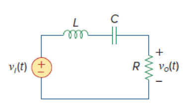
Figure 14.35
Expert Solution & Answer
Want to see the full answer?
Check out a sample textbook solution
Students have asked these similar questions
4.
The Bode plot shown below represents the voltage gain of a particular amplifier. Sketch the input and output waveforms, v,() and
v(1) if the input to the amplifier is v, (1) = 10 + 10cos(400t + 60°) mV. Use the graph paper on the next page for your sketches and
label the minimum and maximum value for each waveform.
60
Bode Diagram
58
56
54
52
50
48
46
44
42
40
-5
-10
-15
-20
-25
-30
-35
-40
-45
-50
-55
-60
100
101
102
Frequency (rad/s)
10
104
105
(Bap) aseud
Magnitude (dB)
Design second order high pass filter to find the value of capacitors if R1 = 23K, R2=11.5K and the cut of frequency is 1KHz
Design second order high pass filter to find the value of capacitors if R1 = 23K, R2=11.5K and the cut of frequency is 1KHz
Please i need it know
Chapter 14 Solutions
Fundamentals of Electric Circuits
Ch. 14.2 - Obtain the transfer function VoVs of the RL...Ch. 14.2 - Prob. 2PPCh. 14.4 - Draw the Bode plots for the transfer function...Ch. 14.4 - Sketch the Bode plots for H()=50j(j+4)(j+10)2Ch. 14.4 - Construct the Bode plots for H(s)=10s(s2+80s+400)Ch. 14.4 - Obtain the transfer function H() corresponding to...Ch. 14.5 - A series-connected circuit has R = 4 and L = 25...Ch. 14.6 - A parallel resonant circuit has R = 100 k, L = 50...Ch. 14.6 - Calculate the resonant frequency of the circuit in...Ch. 14.7 - For the circuit in Fig. 14.40, obtain the transfer...
Ch. 14.7 - Design a band-pass filter of the form in Fig....Ch. 14.8 - Design a high-pass filter with a high-frequency...Ch. 14.8 - Design a notch filter based on Fig. 14.47 for 0 =...Ch. 14.9 - Prob. 14PPCh. 14.10 - Obtain the frequency response of the circuit in...Ch. 14.10 - Consider the network in Fig. 14.57. Use PSpice to...Ch. 14.12 - For an FM radio receiver, the incoming wave is in...Ch. 14.12 - Repeat Example 14.18 for band-pass filter BP6....Ch. 14.12 - If each speaker in Fig. 14.66 has an 8- resistance...Ch. 14 - Prob. 1RQCh. 14 - On the Bode magnitude plot, the slope of 1/5+j2...Ch. 14 - On the Bode phase plot for 0.5 50, the slope of...Ch. 14 - How much inductance is needed to resonate at 5 kHz...Ch. 14 - The difference between the half-power frequencies...Ch. 14 - Prob. 6RQCh. 14 - Prob. 7RQCh. 14 - Prob. 8RQCh. 14 - What kind of filter can be used to select a signal...Ch. 14 - A voltage source supplies a signal of constant...Ch. 14 - Find the transfer function Io/Ii of the RL circuit...Ch. 14 - Using Fig. 14.69, design a problem to help other...Ch. 14 - For the circuit shown in Fig. 14.70, find H(s) =...Ch. 14 - Find the transfer function H(s) = Vo/Vi of the...Ch. 14 - For the circuit shown in Fig. 14.72, find H(s) =...Ch. 14 - For the circuit shown in Fig. 14.73, find H(s) =...Ch. 14 - Calculate |H()| if HdB equals (a) 0.1 dB (b) 5 dB...Ch. 14 - Design a problem to help other students calculate...Ch. 14 - A ladder network has a voltage gain of...Ch. 14 - Design a problem to help other students better...Ch. 14 - Sketch the Bode plots for H()=0.2(10+j)j(2+j)Ch. 14 - A transfer function is given by...Ch. 14 - Construct the Bode plots for...Ch. 14 - Draw the Bode plots for H()=250(j+1)j(2+10j+25)Ch. 14 - Prob. 15PCh. 14 - Sketch Bode magnitude and phase plots for...Ch. 14 - Sketch the Bode plots for G(s)=s(s+2)2(s+1), s = jCh. 14 - A linear network has this transfer function...Ch. 14 - Sketch the asymptotic Bode plots of the magnitude...Ch. 14 - Design a more complex problem than given in Prob....Ch. 14 - Sketch the magnitude Bode plot for...Ch. 14 - Find the transfer function H() with the Bode...Ch. 14 - The Bode magnitude plot of H() is shown in Fig....Ch. 14 - The magnitude plot in Fig. 14.76 represents the...Ch. 14 - A series RLC network has R = 2 k, L = 40 mH, and C...Ch. 14 - Design a problem to help other students better...Ch. 14 - Design a series RLC resonant circuit with 0 = 40...Ch. 14 - Design a series RLC circuit with B = 20 rad/s and...Ch. 14 - Let vs = 20 cos(at) V in the circuit of Fig....Ch. 14 - A circuit consisting of a coil with inductance 10...Ch. 14 - Design a parallel resonant RLC circuit with 0 =...Ch. 14 - Design a problem to help other students better...Ch. 14 - A parallel resonant circuit with a bandwidth of 40...Ch. 14 - A parallel RLC circuit has R = 100 k, L = 100 mH,...Ch. 14 - A parallel RLC circuit has R = 10 k, L = 100 mH,...Ch. 14 - It is expected that a parallel RLC resonant...Ch. 14 - Rework Prob. 14.25 if the elements are connected...Ch. 14 - Find the resonant frequency of the circuit in Fig....Ch. 14 - For the tank circuit in Fig. 14.79, find the...Ch. 14 - Prob. 40PCh. 14 - Using Fig. 14.80, design a problem to help other...Ch. 14 - For the circuits in Fig. 14.81, find the resonant...Ch. 14 - Calculate the resonant frequency of each of the...Ch. 14 - For the circuit in Fig. 14.83, find: (a) the...Ch. 14 - For the circuit shown in Fig. 14.84. find 0, B,...Ch. 14 - For the network illustrated in Fig. 14.85, find...Ch. 14 - Prob. 47PCh. 14 - Find the transfer function Vo/Vs of the circuit in...Ch. 14 - Design a problem to help other students better...Ch. 14 - Determine what type of filter is in Fig. 14.87....Ch. 14 - Design an RL low-pass filter that uses a 40-mH...Ch. 14 - Design a problem to help other students better...Ch. 14 - Design a series RLC type band-pass filter with...Ch. 14 - Design a passive band-stop filter with 0 = 10...Ch. 14 - Determine the range of frequencies that will be...Ch. 14 - (a) Show that for a band-pass filter,...Ch. 14 - Determine the center frequency and bandwidth of...Ch. 14 - The circuit parameters for a series RLC band-stop...Ch. 14 - Find the bandwidth and center frequency of the...Ch. 14 - Obtain the transfer function of a high-pass filter...Ch. 14 - Find the transfer function for each of the active...Ch. 14 - The filter in Fig. 14.90(b) has a 3-dB cutoff...Ch. 14 - Design an active first-order high-pass filter with...Ch. 14 - Obtain the transfer function of the active filter...Ch. 14 - A high-pass filter is shown in Fig. 14.92. Show...Ch. 14 - A general first-order filter is shown in Fig....Ch. 14 - Design an active low-pass filter with dc gain of...Ch. 14 - Design a problem to help other students better...Ch. 14 - Design the filter in Fig. 14.94 to meet the...Ch. 14 - A second-order active filter known as a...Ch. 14 - Use magnitude and frequency scaling on the circuit...Ch. 14 - Design a problem to help other students better...Ch. 14 - Calculate the values of R, L, and C that will...Ch. 14 - Prob. 74PCh. 14 - In an RLC circuit, R = 20 , L = 4 H, and C = 1 F....Ch. 14 - Given a parallel RLC circuit with R = 5 k, L = 10...Ch. 14 - A series RLC circuit has R = 10 , 0 = 40 rad/s,...Ch. 14 - Redesign the circuit in Fig. 14.85 so that all...Ch. 14 - Refer to the network in Fig. 14.96. (a) Find...Ch. 14 - (a) For the circuit in Fig. 14.97, draw the new...Ch. 14 - The circuit shown in Fig. 14.98 has the impedance...Ch. 14 - Scale the low-pass active filter in Fig. 14.99 so...Ch. 14 - The op amp circuit in Fig. 14.100 is to be...Ch. 14 - Using PSpice or MultiSim, obtain the frequency...Ch. 14 - Use PSpice or MultiSim to obtain the magnitude and...Ch. 14 - Using Fig. 14.103, design a problem to help other...Ch. 14 - In the interval 0.1 f 100 Hz, plot the response...Ch. 14 - Use PSpice or MultiSim to generate the magnitude...Ch. 14 - Obtain the magnitude plot of the response Vo in...Ch. 14 - Obtain the frequency response of the circuit in...Ch. 14 - For the tank circuit of Fig. 14.79, obtain the...Ch. 14 - Using PSpice or MultiSim, plot the magnitude of...Ch. 14 - For the phase shifter circuit shown in Fig....Ch. 14 - For an emergency situation, an engineer needs to...Ch. 14 - A series-tuned antenna circuit consists of a...Ch. 14 - The crossover circuit in Fig. 14.108 is a low-pass...Ch. 14 - The crossover circuit in Fig. 14.109 is a...Ch. 14 - A certain electronic test circuit produced a...Ch. 14 - In an electronic device, a series circuit is...Ch. 14 - In a certain application, a simple RC low-pass...Ch. 14 - In an amplifier circuit, a simple RC high-pass...Ch. 14 - Practical RC filter design should allow for source...Ch. 14 - The RC circuit in Fig. 14.111 is used for a lead...Ch. 14 - A low-quality-factor, double-tuned band-pass...
Additional Engineering Textbook Solutions
Find more solutions based on key concepts
Electric power systems provide energy in a variety of commercial and industrial settings. Make a list of system...
Principles and Applications of Electrical Engineering
Find I0 and I1 in the circuit in Fig.P2.12.
Basic Engineering Circuit Analysis
Assume a telephone signal travels through a cable at two-thirds the speed of light. How long does it take the s...
Electric Circuits (10th Edition)
A constant voltage of 10V is applied to a 50H inductance, as shown in Figure P3.51 Figure P3 51 The current in ...
Electrical Engineering: Principles & Applications (7th Edition)
Write the nodal equations for the network of Fig. 8.137 using the general approach. Find the nodal voltages usi...
Introductory Circuit Analysis (13th Edition)
Three point charges of equal magnitude q, that will yield a zero net electric field at the origin.
Engineering Electromagnetics
Knowledge Booster


Learn more about
Need a deep-dive on the concept behind this application? Look no further. Learn more about this topic, electrical-engineering and related others by exploring similar questions and additional content below.Similar questions
- Ex. 590. Refer to Figure 590. R1=7 Ohms R2=1/3 Ohms and C=7 Fd. Find the transfer function V2(s)/V1(s) = A/(s^2+Bs+D). Answers: A,B,D. Active Low-Pass Butterworth Filter C C R1 + R1 v1 (t) v2 (t) R1 R2 Figure 590arrow_forwardIm + Re -100 -1 Figure 1: We want to sketch the bode plot for this filter! 1) Rewrite H(s) in the "standard form" for Bode plots 2) Using paper + pencil, sketch the Bode magnitude and phase shift plots. 3) What kind of filter is this: Low-pass Bandpass High-pass Notcharrow_forwardВ Vin -w Vo Figure 14.91 (Exercise 14.40) Figure 14.91 shows the cascaded RC sections that form the feedback network for the RC phase-shift oscillator. Show that the feedback ratio is Vin с www.m R с с HE R³ (R³ -- 5RX²) + j(X² – 6R²Xc)arrow_forward
- 1. A tuned circuit has a resonant frequency of 18 MHz and a bandwidth of 120 kHz. What are the upper and lower cutoff frequencies?2. What value of Q is needed to achieve a bandwidth of 4 kHz at 3.6 MHz?3. A filter has a 6-dB bandwidth of 3500 Hz and a 60-dB bandwidth of 8400 Hz. What is the shape factor?arrow_forwardPassive filters are made of passive components, tuned to the harmonic frequencies that are to be attenuated. Show that a series LR circuit is a lowpass filter if the output is taken across the resistor.arrow_forwardFollowing figure shows magnitude Bode diagram of a Band Pass Filter 0.5 100 1 10 120 130 Frequency (rad's) Determine the value of inductor and resistor of a parallel RLC circuit which satifies the Bode diagram. Take C=1mF i) Value of inductor in Henries? ii) Value of resistor in Ohms? b) Using first-order prototype filters and cascade connection design a third-order low-pass filter with a cutoff frequency of 3krad/s and a passband gain of OdB. Use 1000Qresistors. i) Determine the cutoff frequency of the third-order cascade prototype filter we3 2. (sp) apnauteyarrow_forward
- VS+ -SA V1 5 V2 5 .ac dec 100 1 1Meg lib LM741.mod VIN V3 R1 C1 1.3k 0.12μ AC 1 Figure. Active Band Pass Filter R2 1.3k C2 0.12μ Imax -VS+ -SA U1 VOUT LM741/NS Provide the following expressions or values as required: VOUT VIN ) Expression for the maximum gain/magnitude G = ) Expression for the natural frequency fo and its corresponding value ) Expression for selectivity Q and its corresponding value and its corresponding valuearrow_forward1. A) B) Write the transfer function for the RC high-pass filter of Figure 2. First write it in terms of jw (or s) and then write it as its magnitude and phase angle. Determine and record below the cutoff frequencies of the circuit. Sketch the straight line approximations of the frequency responses for the RC high-pass filter on Graph Avla 0.1 0 -20 -10 90° 60° 30° 0' -30° -60* -90* e=2 sin (cot) 0 0.2 (a) Voltage gain response 0.5 0.1 0.2 b.² (b) Phase shift response 1 1 R = 75 ohms 2 L=2.4 mH 5 Vout 10 20 10 20 50 50 100 f (kHz) 100 (kHz)arrow_forwardI want the answer in detail and as quickly as possible please Q/ Using capacitors and resistors, design A - (band-pass filters) with Fl=105HZ and Fh=115HZ. B - Design (band-pass filters) with FI = 215HZ and Fh = 225HZ.arrow_forward
- Required information The circuit shown in the given figure is an active filter. Assume C=15 nF. Ro 4 kohm, R₁-1.2 kohm, R₂ =29.4 kohm, and R3=97.7 kohm. NOTE This is a multi-part question. Once an answer is submitted, you will be unable to return to this part. ww www R₁ C Determine the cutoff frequencies www 20 The cutoff frequencies w₁ and 2 are X 103 and 104, 4, respectively.arrow_forwardElectrical Engineering will upvote . Need matlab knowledge these are the parts that need to be answered. ons: Calculate the cutoff points. Show a screenshot of your circuit. Are the calculated cutoffs being reflected on the theoretical Bode Plot? Include a screenshot of your codes and the theoretical Bode Plot with both cutoff points labelled. How well did the filter perform when processing the 10HZ and 15OHZ combined signal? Include a screenshot of the Scope. The transfer function for the band pass filter is given to you (equation 9). How was this derived? Show the steps starting from how you use the circuit to get the equations representing the circuit to how you solve the equations to get the final version. Given is that it is an RC Bandpass circuit with r1=10kohm, r2= 100kohm ,c1=1uf ,c2=0.001uf. the RC bandpass circuit proceeses 10hz and 150 hz combination. equation 9 needed for part 4 mentioned above is wC1 R Vw? (RCi+R1C2+R2C2)²+(1–w?C,C2R, R2)2 %3Darrow_forwardDiscussions: 1) For the following filter, 0.15pF Vout Vin 3300 2) Explain what a band-pass filter is, and how it differs from either a low-pass or a high-pass filter circuit. Also, explain what a band-stop filter is, and draw Bode plots representative of both band-pass and band-stop filter types.arrow_forward
arrow_back_ios
SEE MORE QUESTIONS
arrow_forward_ios
Recommended textbooks for you
 Introductory Circuit Analysis (13th Edition)Electrical EngineeringISBN:9780133923605Author:Robert L. BoylestadPublisher:PEARSON
 Delmar's Standard Textbook Of ElectricityElectrical EngineeringISBN:9781337900348Author:Stephen L. HermanPublisher:Cengage Learning
 Programmable Logic ControllersElectrical EngineeringISBN:9780073373843Author:Frank D. PetruzellaPublisher:McGraw-Hill Education
 Fundamentals of Electric CircuitsElectrical EngineeringISBN:9780078028229Author:Charles K Alexander, Matthew SadikuPublisher:McGraw-Hill Education
 Electric Circuits. (11th Edition)Electrical EngineeringISBN:9780134746968Author:James W. Nilsson, Susan RiedelPublisher:PEARSON
 Engineering ElectromagneticsElectrical EngineeringISBN:9780078028151Author:Hayt, William H. (william Hart), Jr, BUCK, John A.Publisher:Mcgraw-hill Education,
Introductory Circuit Analysis (13th Edition)
Electrical Engineering
ISBN:9780133923605
Author:Robert L. Boylestad
Publisher:PEARSON
Delmar's Standard Textbook Of Electricity
Electrical Engineering
ISBN:9781337900348
Author:Stephen L. Herman
Publisher:Cengage Learning
Programmable Logic Controllers
Electrical Engineering
ISBN:9780073373843
Author:Frank D. Petruzella
Publisher:McGraw-Hill Education
Fundamentals of Electric Circuits
Electrical Engineering
ISBN:9780078028229
Author:Charles K Alexander, Matthew Sadiku
Publisher:McGraw-Hill Education
Electric Circuits. (11th Edition)
Electrical Engineering
ISBN:9780134746968
Author:James W. Nilsson, Susan Riedel
Publisher:PEARSON
Engineering Electromagnetics
Electrical Engineering
ISBN:9780078028151
Author:Hayt, William H. (william Hart), Jr, BUCK, John A.
Publisher:Mcgraw-hill Education,
What is Filter & Classification of Filters | Four Types of Filters | Electronic Devices & Circuits; Author: SimplyInfo;https://www.youtube.com/watch?v=9x1Sjz-VPSg;License: Standard Youtube License