
Fundamentals of Electric Circuits
6th Edition
ISBN: 9780078028229
Author: Charles K Alexander, Matthew Sadiku
Publisher: McGraw-Hill Education
expand_more
expand_more
format_list_bulleted
Concept explainers
Videos
Textbook Question
Chapter 14.12, Problem 19PP
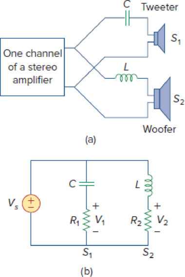
If each speaker in Fig. 14.66 has an 8-Ω resistance and C = 10 μF, find L and the crossover frequency.
Figure 14.66
(a) A crossover network for two loudspeakers, (b) equivalent model.
Expert Solution & Answer
Want to see the full answer?
Check out a sample textbook solution
Students have asked these similar questions
Q6. What is the purpose of harmonic standards? Provide a
summary of comparison of IEEE and IEC standards. Write the
purpose of the following international standards shown in Table-
2:
[12]
Table-2
Sr No
1 IEEE-18
Standards
Description
2
IEEE 518
3
IEEE 519
4
IEEE 1159
5
IEEE P1433
6.
IEEE P1453
7
IEEE P1564
8
IEC61000-3-2
9
IEC 61000-4-7
10 IEC 61642
11 IEC SC77A/WG9
12 IEC SC77A/WG2
Desing a lattice attenuator to have characteristic impedance of 800 Q and
attenuation of 20 dB.
In a RC type low pass fitter, the cut-off
frequency is 1500 Hz, Assuming the
capacitance to be 500 nF. The value of
the resistance is - (in)
Chapter 14 Solutions
Fundamentals of Electric Circuits
Ch. 14.2 - Obtain the transfer function VoVs of the RL...Ch. 14.2 - Prob. 2PPCh. 14.4 - Draw the Bode plots for the transfer function...Ch. 14.4 - Sketch the Bode plots for H()=50j(j+4)(j+10)2Ch. 14.4 - Construct the Bode plots for H(s)=10s(s2+80s+400)Ch. 14.4 - Obtain the transfer function H() corresponding to...Ch. 14.5 - A series-connected circuit has R = 4 and L = 25...Ch. 14.6 - A parallel resonant circuit has R = 100 k, L = 50...Ch. 14.6 - Calculate the resonant frequency of the circuit in...Ch. 14.7 - For the circuit in Fig. 14.40, obtain the transfer...
Ch. 14.7 - Design a band-pass filter of the form in Fig....Ch. 14.8 - Design a high-pass filter with a high-frequency...Ch. 14.8 - Design a notch filter based on Fig. 14.47 for 0 =...Ch. 14.9 - Prob. 14PPCh. 14.10 - Obtain the frequency response of the circuit in...Ch. 14.10 - Consider the network in Fig. 14.57. Use PSpice to...Ch. 14.12 - For an FM radio receiver, the incoming wave is in...Ch. 14.12 - Repeat Example 14.18 for band-pass filter BP6....Ch. 14.12 - If each speaker in Fig. 14.66 has an 8- resistance...Ch. 14 - Prob. 1RQCh. 14 - On the Bode magnitude plot, the slope of 1/5+j2...Ch. 14 - On the Bode phase plot for 0.5 50, the slope of...Ch. 14 - How much inductance is needed to resonate at 5 kHz...Ch. 14 - The difference between the half-power frequencies...Ch. 14 - Prob. 6RQCh. 14 - Prob. 7RQCh. 14 - Prob. 8RQCh. 14 - What kind of filter can be used to select a signal...Ch. 14 - A voltage source supplies a signal of constant...Ch. 14 - Find the transfer function Io/Ii of the RL circuit...Ch. 14 - Using Fig. 14.69, design a problem to help other...Ch. 14 - For the circuit shown in Fig. 14.70, find H(s) =...Ch. 14 - Find the transfer function H(s) = Vo/Vi of the...Ch. 14 - For the circuit shown in Fig. 14.72, find H(s) =...Ch. 14 - For the circuit shown in Fig. 14.73, find H(s) =...Ch. 14 - Calculate |H()| if HdB equals (a) 0.1 dB (b) 5 dB...Ch. 14 - Design a problem to help other students calculate...Ch. 14 - A ladder network has a voltage gain of...Ch. 14 - Design a problem to help other students better...Ch. 14 - Sketch the Bode plots for H()=0.2(10+j)j(2+j)Ch. 14 - A transfer function is given by...Ch. 14 - Construct the Bode plots for...Ch. 14 - Draw the Bode plots for H()=250(j+1)j(2+10j+25)Ch. 14 - Prob. 15PCh. 14 - Sketch Bode magnitude and phase plots for...Ch. 14 - Sketch the Bode plots for G(s)=s(s+2)2(s+1), s = jCh. 14 - A linear network has this transfer function...Ch. 14 - Sketch the asymptotic Bode plots of the magnitude...Ch. 14 - Design a more complex problem than given in Prob....Ch. 14 - Sketch the magnitude Bode plot for...Ch. 14 - Find the transfer function H() with the Bode...Ch. 14 - The Bode magnitude plot of H() is shown in Fig....Ch. 14 - The magnitude plot in Fig. 14.76 represents the...Ch. 14 - A series RLC network has R = 2 k, L = 40 mH, and C...Ch. 14 - Design a problem to help other students better...Ch. 14 - Design a series RLC resonant circuit with 0 = 40...Ch. 14 - Design a series RLC circuit with B = 20 rad/s and...Ch. 14 - Let vs = 20 cos(at) V in the circuit of Fig....Ch. 14 - A circuit consisting of a coil with inductance 10...Ch. 14 - Design a parallel resonant RLC circuit with 0 =...Ch. 14 - Design a problem to help other students better...Ch. 14 - A parallel resonant circuit with a bandwidth of 40...Ch. 14 - A parallel RLC circuit has R = 100 k, L = 100 mH,...Ch. 14 - A parallel RLC circuit has R = 10 k, L = 100 mH,...Ch. 14 - It is expected that a parallel RLC resonant...Ch. 14 - Rework Prob. 14.25 if the elements are connected...Ch. 14 - Find the resonant frequency of the circuit in Fig....Ch. 14 - For the tank circuit in Fig. 14.79, find the...Ch. 14 - Prob. 40PCh. 14 - Using Fig. 14.80, design a problem to help other...Ch. 14 - For the circuits in Fig. 14.81, find the resonant...Ch. 14 - Calculate the resonant frequency of each of the...Ch. 14 - For the circuit in Fig. 14.83, find: (a) the...Ch. 14 - For the circuit shown in Fig. 14.84. find 0, B,...Ch. 14 - For the network illustrated in Fig. 14.85, find...Ch. 14 - Prob. 47PCh. 14 - Find the transfer function Vo/Vs of the circuit in...Ch. 14 - Design a problem to help other students better...Ch. 14 - Determine what type of filter is in Fig. 14.87....Ch. 14 - Design an RL low-pass filter that uses a 40-mH...Ch. 14 - Design a problem to help other students better...Ch. 14 - Design a series RLC type band-pass filter with...Ch. 14 - Design a passive band-stop filter with 0 = 10...Ch. 14 - Determine the range of frequencies that will be...Ch. 14 - (a) Show that for a band-pass filter,...Ch. 14 - Determine the center frequency and bandwidth of...Ch. 14 - The circuit parameters for a series RLC band-stop...Ch. 14 - Find the bandwidth and center frequency of the...Ch. 14 - Obtain the transfer function of a high-pass filter...Ch. 14 - Find the transfer function for each of the active...Ch. 14 - The filter in Fig. 14.90(b) has a 3-dB cutoff...Ch. 14 - Design an active first-order high-pass filter with...Ch. 14 - Obtain the transfer function of the active filter...Ch. 14 - A high-pass filter is shown in Fig. 14.92. Show...Ch. 14 - A general first-order filter is shown in Fig....Ch. 14 - Design an active low-pass filter with dc gain of...Ch. 14 - Design a problem to help other students better...Ch. 14 - Design the filter in Fig. 14.94 to meet the...Ch. 14 - A second-order active filter known as a...Ch. 14 - Use magnitude and frequency scaling on the circuit...Ch. 14 - Design a problem to help other students better...Ch. 14 - Calculate the values of R, L, and C that will...Ch. 14 - Prob. 74PCh. 14 - In an RLC circuit, R = 20 , L = 4 H, and C = 1 F....Ch. 14 - Given a parallel RLC circuit with R = 5 k, L = 10...Ch. 14 - A series RLC circuit has R = 10 , 0 = 40 rad/s,...Ch. 14 - Redesign the circuit in Fig. 14.85 so that all...Ch. 14 - Refer to the network in Fig. 14.96. (a) Find...Ch. 14 - (a) For the circuit in Fig. 14.97, draw the new...Ch. 14 - The circuit shown in Fig. 14.98 has the impedance...Ch. 14 - Scale the low-pass active filter in Fig. 14.99 so...Ch. 14 - The op amp circuit in Fig. 14.100 is to be...Ch. 14 - Using PSpice or MultiSim, obtain the frequency...Ch. 14 - Use PSpice or MultiSim to obtain the magnitude and...Ch. 14 - Using Fig. 14.103, design a problem to help other...Ch. 14 - In the interval 0.1 f 100 Hz, plot the response...Ch. 14 - Use PSpice or MultiSim to generate the magnitude...Ch. 14 - Obtain the magnitude plot of the response Vo in...Ch. 14 - Obtain the frequency response of the circuit in...Ch. 14 - For the tank circuit of Fig. 14.79, obtain the...Ch. 14 - Using PSpice or MultiSim, plot the magnitude of...Ch. 14 - For the phase shifter circuit shown in Fig....Ch. 14 - For an emergency situation, an engineer needs to...Ch. 14 - A series-tuned antenna circuit consists of a...Ch. 14 - The crossover circuit in Fig. 14.108 is a low-pass...Ch. 14 - The crossover circuit in Fig. 14.109 is a...Ch. 14 - A certain electronic test circuit produced a...Ch. 14 - In an electronic device, a series circuit is...Ch. 14 - In a certain application, a simple RC low-pass...Ch. 14 - In an amplifier circuit, a simple RC high-pass...Ch. 14 - Practical RC filter design should allow for source...Ch. 14 - The RC circuit in Fig. 14.111 is used for a lead...Ch. 14 - A low-quality-factor, double-tuned band-pass...
Knowledge Booster


Learn more about
Need a deep-dive on the concept behind this application? Look no further. Learn more about this topic, electrical-engineering and related others by exploring similar questions and additional content below.Similar questions
- A step up dc/dc converter has input voltage Vs = 9 V, the average output voltage Va = 15 average load current la = 0.8 A. The switching frequency is f = 20 kHz, inductance is L = 0.3 mH and the parallel capacitance is C = 0.44 mF. Which one is the ripple current of inductor, Al ?arrow_forwardq13,q14arrow_forwardThis approach is a reduced version of the hybrid pi model used almost exclusively for high-frequency analysis. a.re b.T c.hybrid-T d.hybridarrow_forward
- (b) Draw the circuit diagram of step-down chopper, also draw the waveforms of source voltage Vs and output voltage V. for duty ratio a = 0•4 and time period T = 10 us.arrow_forward1.Without bypass capacitor CE, determine output impedance Zo2.Without bypass capacitor CE, determine VBC3.Find Zo4.Determine VBCarrow_forwardAntenna Tank Circuit L Germanium Amplifier Diode To Speakers 12 pF - 120 pF Vout 100 ka R2 RI { Low Pass Filter Figure 4 Figure 4 shows a radio receiver circuit. The antenna that receives radio signals can be modelled as an AC current source, I.. The antenna is connected to a "Tank Circuit" that consist of an inductor with inductance L, and a variable capacitor, and then connected to the ground. When the capacitor is tuncd to the right value, a very high voltage Vo is generated to send signals through the Germanium diode, and the signals are passed into an amplifier system and then converted to sound in the speakers. If the inductance L is given as 1.0 miero-Henries, determine the capacitance values (in pico- Farads) to tune to your favourite Radio Stations in Malaysia listed in the table below: Radio Station Frequency, Angular Tuned Name f Frequency, o Capacitance, pF 988 FM Best FM 98.8 MHz 104.1 MHz Mutiara FM 95.7 MHz Nasional FM 88.5 MHzarrow_forward
- Various parameters of Schering bridge are given as follows. The voltage supply of 2 kHz is connected to terminals A and C and detector to points B and D. Arm AB comprises the unknown Resistor R1 and capacitor C1. Arm BC consists of resistor R2 of 18k 2. Arm DA consists of capacitor C2 of 0.06 µf. Arm CD has R3 of 1.5kſN and C3 of 2nf are in parallel. Calculate (i) the capacitance (C1) (ii) the equivalent series resistance (R1) and (iii) dissipation factor. Also draw the schematic diagram.arrow_forwardA step up dc/dc converter has input voltage Vs = 9 V, the average output voltage Va = 15 average load current lg = 0.8 A. The switching frequency is f = 20 kHz, inductance is L = 0.3 mH and the parallel capacitance is C= 0.44 mF. Which one is the ripple current of inductor, AI ?arrow_forwardH.W: A resistor of resistance R=1000 2is maintained at 17 °C and it shunted by 100 uH inductor. Determine the ms noise voltage across the inductor over a frequency bandwi dth of: Ans: 182 x10° volt Ans: 9.22 x10 volt Ans: 2.34 x10 volt i) 15.9 kHz ii) i) 159 kHz 1590 kHzarrow_forward
- A:11 A docs.google.com For positive half of the signal below, what is the peak output value of the circuit? NOTE: use silicon diode. * 20 V 10V -20 V O 3.3 O -10.3 50.7 29.3 32.3 like that of the clipper, the shape of the input signals of a clamper is changed. * O F От For the given circuit for a 40 V (p-p) sinusoidal input vi, what is the value of vi at which the clipping begIs: v-ov. NOTE: usearrow_forward7- Frequency can be measured using: a- Maxwell bridge. b- Wheatstone bridge. d-wien bridge. c-kelvin bridge. 8- In wien's bridge, the output frequency is determined by: a-LC combination. b-RL combination. c-RLC combination. d-RC combination. 9- A moving coil instrument has a resistance of 0.6 2 and full-scale deflection at 0.1 A. To convert it into an ammeter of 0-15 A range, the resistance of shunt should be a-0.62 b-0.06 2 d- 0.004 Ω c-0.1 Ω 10- The basic component of digital voltmeter are: a- A\D converter and a counter. c-D\A converter and a counter. b- AD converter and a rectifier. d- Ramp generator and a counter. 11- A d.c voltmeter has a sensitivity of 1000 2/V when it measures half full scale in 100V range, the current through the voltmeter is: a- 100mA b- IMA c-0.5mA d- 50mA 12- A DVM measure... a- peak value. b- RMS value. c- Average value. d- peak to peak value. 13. The study of energy distribution across the frequency spectrum of a given electrical signal is done by a a-…arrow_forwardThe input impedance is equal to the .... ,load impedance (Zin=ZL) when L=\/10 O none O L=\/4 O L=\/2 Oarrow_forward
arrow_back_ios
SEE MORE QUESTIONS
arrow_forward_ios
Recommended textbooks for you
 Introductory Circuit Analysis (13th Edition)Electrical EngineeringISBN:9780133923605Author:Robert L. BoylestadPublisher:PEARSON
 Delmar's Standard Textbook Of ElectricityElectrical EngineeringISBN:9781337900348Author:Stephen L. HermanPublisher:Cengage Learning
 Programmable Logic ControllersElectrical EngineeringISBN:9780073373843Author:Frank D. PetruzellaPublisher:McGraw-Hill Education
 Fundamentals of Electric CircuitsElectrical EngineeringISBN:9780078028229Author:Charles K Alexander, Matthew SadikuPublisher:McGraw-Hill Education
 Electric Circuits. (11th Edition)Electrical EngineeringISBN:9780134746968Author:James W. Nilsson, Susan RiedelPublisher:PEARSON
 Engineering ElectromagneticsElectrical EngineeringISBN:9780078028151Author:Hayt, William H. (william Hart), Jr, BUCK, John A.Publisher:Mcgraw-hill Education,
Introductory Circuit Analysis (13th Edition)
Electrical Engineering
ISBN:9780133923605
Author:Robert L. Boylestad
Publisher:PEARSON
Delmar's Standard Textbook Of Electricity
Electrical Engineering
ISBN:9781337900348
Author:Stephen L. Herman
Publisher:Cengage Learning
Programmable Logic Controllers
Electrical Engineering
ISBN:9780073373843
Author:Frank D. Petruzella
Publisher:McGraw-Hill Education
Fundamentals of Electric Circuits
Electrical Engineering
ISBN:9780078028229
Author:Charles K Alexander, Matthew Sadiku
Publisher:McGraw-Hill Education
Electric Circuits. (11th Edition)
Electrical Engineering
ISBN:9780134746968
Author:James W. Nilsson, Susan Riedel
Publisher:PEARSON
Engineering Electromagnetics
Electrical Engineering
ISBN:9780078028151
Author:Hayt, William H. (william Hart), Jr, BUCK, John A.
Publisher:Mcgraw-hill Education,
TRANSFORMERS - What They Are, How They Work, How Electricians Size Them; Author: Electrician U;https://www.youtube.com/watch?v=tXPy4OE7ApE;License: Standard Youtube License