Concept explainers
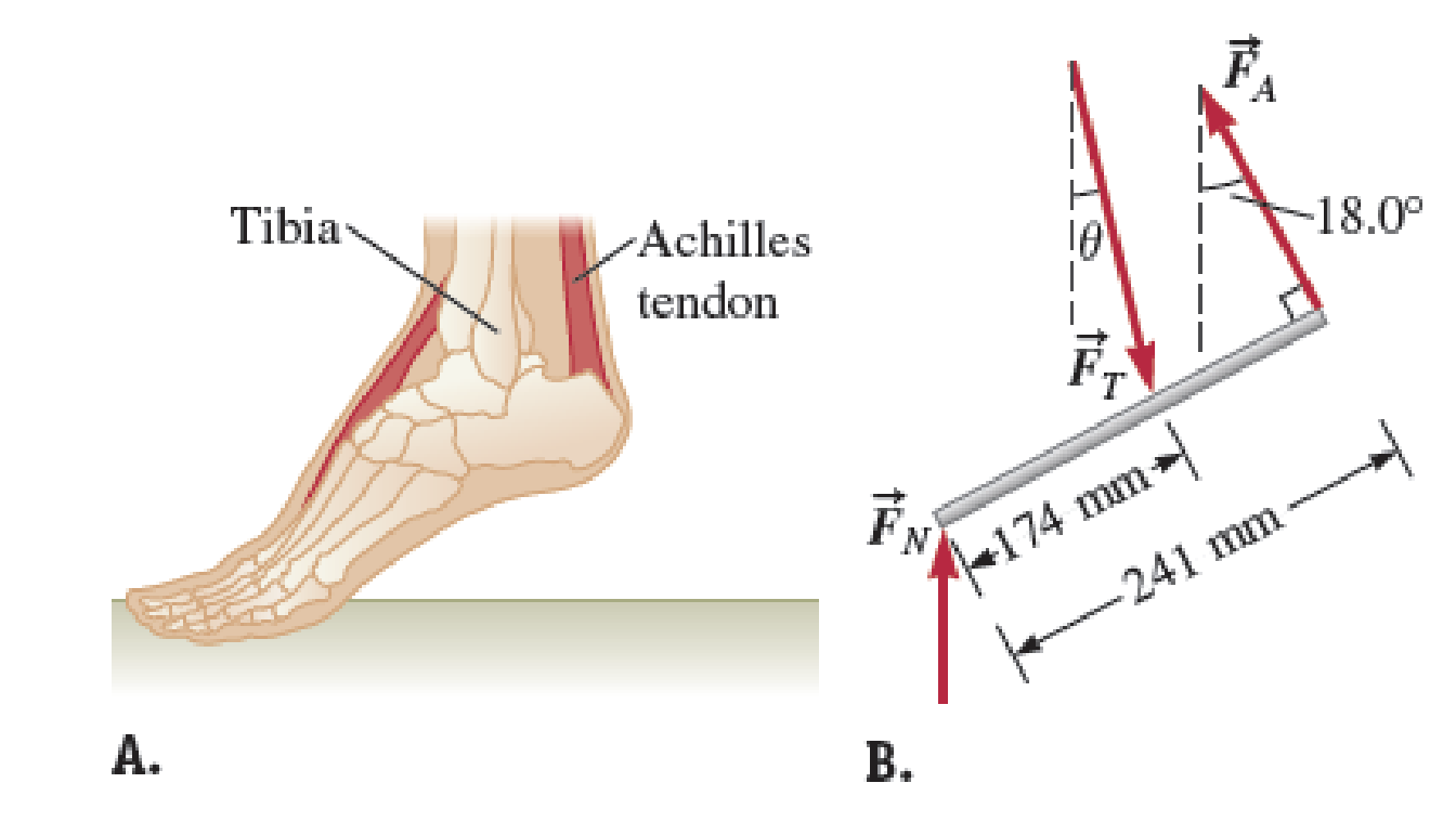
Ruby, with mass 55.0 kg, is trying to reach a box on a high shelf by standing on her tiptoes. In this position, half her weight is supported by the normal force exerted by the floor on the toes of each foot as shown in Figure P14.75A. This situation can be modeled mechanically by representing the force on Ruby’s Achilles tendon with

FIGURE P14.75
Want to see the full answer?
Check out a sample textbook solution
Chapter 14 Solutions
Physics for Scientists and Engineers: Foundations and Connections
- suggest a reason ultrasound cleaning is better than cleaning by hand?arrow_forwardCheckpoint 4 The figure shows four orientations of an electric di- pole in an external electric field. Rank the orienta- tions according to (a) the magnitude of the torque on the dipole and (b) the potential energy of the di- pole, greatest first. (1) (2) E (4)arrow_forwardWhat is integrated science. What is fractional distillation What is simple distillationarrow_forward
- 19:39 · C Chegg 1 69% ✓ The compound beam is fixed at Ę and supported by rollers at A and B. There are pins at C and D. Take F=1700 lb. (Figure 1) Figure 800 lb ||-5- F 600 lb بتا D E C BO 10 ft 5 ft 4 ft-—— 6 ft — 5 ft- Solved Part A The compound beam is fixed at E and... Hình ảnh có thể có bản quyền. Tìm hiểu thêm Problem A-12 % Chia sẻ kip 800 lb Truy cập ) D Lưu of C 600 lb |-sa+ 10ft 5ft 4ft6ft D E 5 ft- Trying Cheaa Những kết quả này có hữu ích không? There are pins at C and D To F-1200 Egue!) Chegg Solved The compound b... Có Không ☑ ||| Chegg 10 וחarrow_forwardNo chatgpt pls will upvotearrow_forwardNo chatgpt pls will upvotearrow_forward
- No chatgpt pls will upvotearrow_forwardair is pushed steadily though a forced air pipe at a steady speed of 4.0 m/s. the pipe measures 56 cm by 22 cm. how fast will air move though a narrower portion of the pipe that is also rectangular and measures 32 cm by 22 cmarrow_forwardNo chatgpt pls will upvotearrow_forward
- 13.87 ... Interplanetary Navigation. The most efficient way to send a spacecraft from the earth to another planet is by using a Hohmann transfer orbit (Fig. P13.87). If the orbits of the departure and destination planets are circular, the Hohmann transfer orbit is an elliptical orbit whose perihelion and aphelion are tangent to the orbits of the two planets. The rockets are fired briefly at the depar- ture planet to put the spacecraft into the transfer orbit; the spacecraft then coasts until it reaches the destination planet. The rockets are then fired again to put the spacecraft into the same orbit about the sun as the destination planet. (a) For a flight from earth to Mars, in what direction must the rockets be fired at the earth and at Mars: in the direction of motion, or opposite the direction of motion? What about for a flight from Mars to the earth? (b) How long does a one- way trip from the the earth to Mars take, between the firings of the rockets? (c) To reach Mars from the…arrow_forwardNo chatgpt pls will upvotearrow_forwarda cubic foot of argon at 20 degrees celsius is isentropically compressed from 1 atm to 425 KPa. What is the new temperature and density?arrow_forward
 Physics for Scientists and EngineersPhysicsISBN:9781337553278Author:Raymond A. Serway, John W. JewettPublisher:Cengage Learning
 Physics for Scientists and Engineers with Modern ...PhysicsISBN:9781337553292Author:Raymond A. Serway, John W. JewettPublisher:Cengage Learning
 Physics for Scientists and Engineers: Foundations...PhysicsISBN:9781133939146Author:Katz, Debora M.Publisher:Cengage Learning
 College PhysicsPhysicsISBN:9781285737027Author:Raymond A. Serway, Chris VuillePublisher:Cengage Learning
 Principles of Physics: A Calculus-Based TextPhysicsISBN:9781133104261Author:Raymond A. Serway, John W. JewettPublisher:Cengage Learning
 Physics for Scientists and Engineers, Technology ...PhysicsISBN:9781305116399Author:Raymond A. Serway, John W. JewettPublisher:Cengage Learning


