Concept explainers
(a)
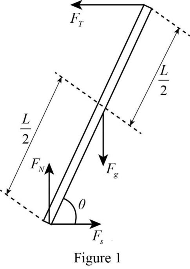
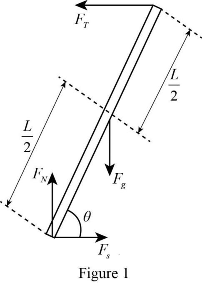
The free-body diagram of the forces acting on the ladder.
(a)
Answer to Problem 82PQ
The free-body diagram of the forces acting on the ladder is

Explanation of Solution
A free-body diagram is a graphical tool used to illustrate the different forces acting on a particular object. It helps to solve complex physical problems. The free-body diagram of the ladder in the given situation is drawn in figure 1.

The forces acting on the ladder are the weight, the normal force, the tension and the force of static friction. In the figure weight is represented as Fg, normal force is denoted as FN, tension is denoted as FT and the force of static friction is denoted by Fs .
Conclusion:
Thus, the free-body diagram of the forces acting on the ladder is drawn in figure 1.
(b)
The tension in the rope in terms of M,g and θ if the ladder is in
(b)
Answer to Problem 82PQ
The tension in the rope in terms of M,g and θ if the ladder is in rotational equilibrium is Mg2cotθ .
Explanation of Solution
Take the lower end of the ladder as the pivot point. This will eliminate the torque due to normal force and the torque due to force of static friction.
Since the ladder is in rotational equilibrium, the net torque about the lower end of the ladder must be zero.
Write the condition for the rotational equilibrium.
∑τlower end=0 (I)
Here, ∑τlower end is the magnitude of the net torque about the lower end of the ladder.
Write the equation for ∑τlower end .
∑τlower end=τN+τs+τg+τT
Here, τN is the magnitude torque due to the normal force about the lower end of the ladder, τs is the magnitude torque due to the static friction about the lower end of the ladder, τg is the magnitude torque due to the weight about the lower end of the ladder and τT is the magnitude torque due to the tension about the lower end of the ladder.
Put the above equation in equation (I).
τN+τs+τg+τT=0 (II)
Write the expression for τN .
τN=0
Write the expression for τs .
τs=0
Write the expression for τg .
τg=−Mg(L2cosθ)
Here, M is the mass of the ladder, g is the acceleration due to gravity, L is the length of the ladder and θ is the angle the ladder makes with the floor.
Write the expression for τT .
τT=FT(Lsinθ)
Here, FT is the magnitude of the tension in the rope.
Put the above four equations in equation (II) and rewrite it for FT .
0+0+(−Mg(L2cosθ))+FT(Lsinθ)=0FTLsinθ=MgL2cosθFT=Mg2cosθsinθ=Mg2cotθ (III)
Conclusion:
Therefore, the tension in the rope in terms of M,g and θ if the ladder is in rotational equilibrium is Mg2cotθ .
(c)
The expression for the tension in the rope in terms of μs,M and g by considering the ladder in
(c)
Answer to Problem 82PQ
The expression for the tension in the rope in terms of μs,M and g by considering the ladder in translational equilibrium is μsMg .
Explanation of Solution
Since the ladder is in translational equilibrium, the net force in x and y directions must be zero.
Write the conditions for the translational equilibrium.
∑Fx=0 (IV)
Here, ∑Fx is the net force in x direction.
∑Fy=0 (V)
Here, ∑Fy is the net force in y direction.
Write the equation for ∑Fx .
∑Fx=−FT+Fs (VI)
Here, Fs is the force of static friction.
Write the equation for Fs .
Fs=μsFN
Here, μs is the coefficient of static friction and FN is the normal force.
Put the above equation in equation (VI).
∑Fx=−FT+μsFN
Put the above equation in equation (IV) and rewrite it for FT .
−FT+μsFN=0FT=μsFN (VII)
Write the equation for ∑Fy .
∑Fy=FN−Fg (VIII)
Here, Fg is the weight of the ladder.
Write the equation for Fg .
Fg=Mg
Put the above equation in equation (VIII).
∑Fy=FN−Mg
Put the above equation in equation (V) and rewrite it for FN .
FN−Mg=0FN=Mg
Put the above equation in equation (VII).
FT=μsMg (IX)
Conclusion:
Therefore, the expression for the tension in the rope in terms of μs,M and g by considering the ladder in translational equilibrium is μsMg .
(d)
The coefficient of static friction in terms of the angle θ .
(d)
Answer to Problem 82PQ
The coefficient of static friction in terms of the angle θ is cotθ2 .
Explanation of Solution
Equate equations (III) and (IX).
Mg2cotθ=μsMgμs=cotθ2
Conclusion:
Therefore, the coefficient of static friction in terms of the angle θ is cotθ2 .
(e)
The after effect of moving the ladder slightly so as to reduce the angle θ .
(e)
Answer to Problem 82PQ
The ladder will slip if it is moved slightly to reduce the angle θ .
Explanation of Solution
The expression for the angle θ obtained in part (d), cotθ2 is valid only at the critical angle θ . The critical angle is the angle when the ladder is on the verge of slipping and the frictional force has its maximum possible value. The angle θ will be reduced when the ladder is moved to the left.
The expression for the tension force obtained in part (b), FT=Mg2cotθ shows that as the value of θ decreases, the tension force will also increases. For the ladder to be in translational equilibrium, the net force in the x direction must be zero. Increasing the tension force will require a larger friction force to balance this condition. But the static friction force is already at its maximum value. This implies, when the ladder is slightly moved to reduce the angle θ, the ladder will slip.
Conclusion:
Thus, the ladder will slip if it is moved slightly to reduce the angle θ .
Want to see more full solutions like this?
Chapter 14 Solutions
Physics for Scientists and Engineers: Foundations and Connections
- please answer this asap!!!!arrow_forwardRT = 4.7E-30 18V IT = 2.3E-3A+ 12 38Ω ли 56Ω ли r5 27Ω ли r3 28Ω r4 > 75Ω r6 600 0.343V 75.8A Now figure out how much current in going through the r4 resistor. |4 = unit And then use that current to find the voltage drop across the r resistor. V4 = unitarrow_forward7 Find the volume inside the cone z² = x²+y², above the (x, y) plane, and between the spheres x²+y²+z² = 1 and x² + y²+z² = 4. Hint: use spherical polar coordinates.arrow_forward
- ганм Two long, straight wires are oriented perpendicular to the page, as shown in the figure(Figure 1). The current in one wire is I₁ = 3.0 A, pointing into the page, and the current in the other wire is 12 4.0 A, pointing out of the page. = Find the magnitude and direction of the net magnetic field at point P. Express your answer using two significant figures. VO ΜΕ ΑΣΦ ? Figure P 5.0 cm 5.0 cm ₁ = 3.0 A 12 = 4.0 A B: μΤ You have already submitted this answer. Enter a new answer. No credit lost. Try again. Submit Previous Answers Request Answer 1 of 1 Part B X Express your answer using two significant figures. ΜΕ ΑΣΦ 0 = 0 ? below the dashed line to the right P You have already submitted this answer. Enter a new answer. No credit lost. Try again.arrow_forwardAn infinitely long conducting cylindrical rod with a positive charge λ per unit length is surrounded by a conducting cylindrical shell (which is also infinitely long) with a charge per unit length of −2λ and radius r1, as shown in the figure. What is σinner, the surface charge density (charge per unit area) on the inner surface of the conducting shell? What is σouter, the surface charge density on the outside of the conducting shell? (Recall from the problem statement that the conducting shell has a total charge per unit length given by −2λ.)arrow_forwardA small conducting spherical shell with inner radius aa and outer radius b is concentric with a larger conducting spherical shell with inner radius c and outer radius d (Figure 1). The inner shell has total charge +2q, and the outer shell has charge −2q. What's the total charge on the inner surface of the small shell? What's the total charge on the outer surface of the small shell? What's the total charge on the inner surface of the large shell? What's the total charge on the outer surface of the large shell?arrow_forward
 Physics for Scientists and Engineers: Foundations...PhysicsISBN:9781133939146Author:Katz, Debora M.Publisher:Cengage Learning
 Physics for Scientists and EngineersPhysicsISBN:9781337553278Author:Raymond A. Serway, John W. JewettPublisher:Cengage Learning
 Physics for Scientists and Engineers with Modern ...PhysicsISBN:9781337553292Author:Raymond A. Serway, John W. JewettPublisher:Cengage Learning
 College PhysicsPhysicsISBN:9781305952300Author:Raymond A. Serway, Chris VuillePublisher:Cengage Learning
 Principles of Physics: A Calculus-Based TextPhysicsISBN:9781133104261Author:Raymond A. Serway, John W. JewettPublisher:Cengage Learning
 College PhysicsPhysicsISBN:9781285737027Author:Raymond A. Serway, Chris VuillePublisher:Cengage Learning


