Concept explainers
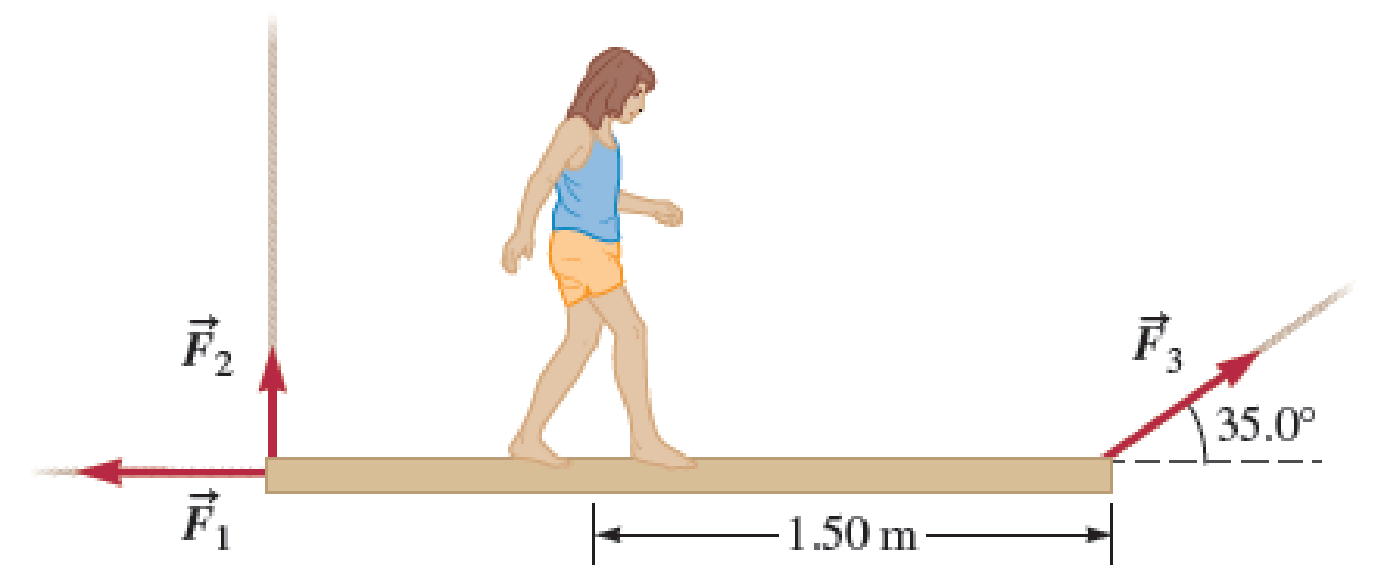
Children playing pirates have suspended a uniform wooden plank with mass 15.0 kg and length 2.50 m as shown in Figure P14.27. What is the tension in each of the three ropes when Sophia, with a mass of 23.0 kg, is made to “walk the plank” and is 1.50 m from reaching the end of the plank?

FIGURE P14.27
The tension in each of the three ropes when S with mass of
Answer to Problem 27PQ
The tension in rope1 is
Explanation of Solution
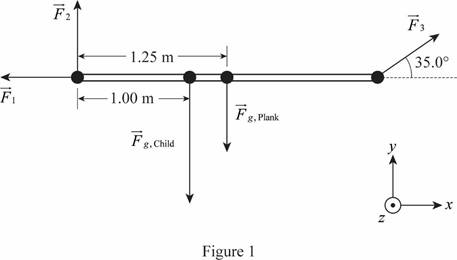
The free body diagram is given below.

Here,
At equilibrium, the sum of forces and sum of torques must be zero.
Consider torque about an axis perpendicular to the page and through the left end of the plank.
Write the equilibrium condition for the torque about an axis perpendicular to the page and through the left end of the plank.
Here,
Since forces
Write the expression for the torque due to a force.
Here,
The forces
Write expression for the net torque about an axis perpendicular to the page and through the left end of the plank.
Here,
Write the expression for
Here,
Write the expression for
Here,
Substitute equation (III) and (IV) in (II) to get
Substitute above equation in equation (I) to get expression for
Write the equilibrium condition of the force along
Here,
Write expression for net force along
Here,
Substitute (VII) in (VI) to get
Write the equilibrium condition of the forces along
Here,
Write net forces along
Here,
Substitute (III) and (IV)in (X) to get
Substitute (XI) in (IX) to get
Conclusion:
Substitute
Substitute
Substitute
Therefore, the tension in rope1 is
Want to see more full solutions like this?
Chapter 14 Solutions
Physics for Scientists and Engineers: Foundations and Connections
- Please solvearrow_forwardPlease solvearrow_forwardA piece of silicon semiconductor has length L=0.01cm and cross-section in a square shape with an area of A=5×10⁻⁴cm2 . The semiconductor is doped with 1012cm−3 Phosphorus atoms and 1017cm−3 Boron atoms. An external electric field E=1.5×10⁴N/C is applied to the silicon piece along the length direction, through the cross section. What is the total current in the silicon at T=300K? Assume the mobility of silicon is 1400cm2V−1s−1 for electrons and 450cm2V−1s−1 for holes, respectively. Assume the intrinsic carrier concentration in silicon is 1010cm−3 . Give your answer in mA, rounded to 3 significant figures. Just enter the number, nothing else.arrow_forward
- An impurity with a charge of 2e is placed in a three-dimensional metal. Assume that the Friedel sum rule holds for this system, and only the scattering phase shifts from the electrons contribute to this sum (we don't need to consider ion phase shifts). This metal has a spherical Fermi surface with Fermi wave vector kF . The only degeneracy for the electrons at the Fermi surface is spin (two-fold) and angular momentum ( 2l+1 for each angular momentum l ). Ignore scattering for l>2 and assume that the scattering doesn't depend on the spin degree of freedom. Denote the scattering phase shift at the Fermi wave vector in the l -th angular momentum channel as δl(kF) . If δ0(kF)=11π31 , and δ1(kF)=π29 , what is δ2(kF)? Round your answer to three significant figures. Just enter the number, nothing else.arrow_forwardA pilot with a mass of 75 kg is flying an airplane at a true airspeed of 55m/s in air that is still relative to the ground. The pilot enters a coordinated turn of constant bank angle and constant altitude, and the pilot experiences an effective weight of 1471.5N normal to the wings of the plane. What is the rate of turn (in degrees per second) for the aircraft? Round your answer to three significant figures. Just enter the number, nothing else.arrow_forwardImagine you are out for a stroll on a sunny day when you encounter a lake. Unpolarized light from the sun is reflected off the lake into your eyes. However, you notice when you put on your vertically polarized sunglasses, the light reflected off the lake no longer reaches your eyes. What is the angle between the unpolarized light and the surface of the water, in degrees, measured from the horizontal? You may assume the index of refraction of air is nair=1 and the index of refraction of water is nwater=1.33 . Round your answer to three significant figures. Just enter the number, nothing else.arrow_forward
- Red, yellow, green, and blue light with wavelengths of λred=700 nm , λyellow=580 nm , λgreen=520 nm , and λblue=475 nm are directed at a slit that is 20 μm wide at normal incidence. The light hits a screen 1 m behind the slit. Which color of light will have an interference minimum closest to a point 10 cm away from its central maxima? You may assume the small angle approximation sinθ≈tanθ≈θ for angles smaller than 10∘ . Just enter the wavelength of that color in nm, nothing else.arrow_forwardIn the circuit shown, the switch is initially open and the capacitor isuncharged. What will be the current through R1 the instant after the switch isclosed? Take V=10 V, R1 = 20 W, R2 = 20 W, R3 = 10 W and C = 2 mF.arrow_forwardIn the circuit shown take: V1 = 20V, V2 = 40V, R1 = 5W, R2 = 2W and R3 =10W. If i1 = 2A, what is i3 if the assumed direction of the current is as shown.arrow_forward
- Consider the circuit shown in the figure below. (Let R = 12.0 (2.) 25.0 V 10.0 www 10.0 Ω b www 5.00 Ω w R 5.00 Ω i (a) Find the current in the 12.0-0 resistor. 1.95 × This is the total current through the battery. Does all of this go through R? A (b) Find the potential difference between points a and b. 1.72 × How does the potential difference between points a and b relate to the current through resistor R? Varrow_forward3.90 ... CP A rocket designed to place small payloads into orbit is carried to an altitude of 12.0 km above sea level by a converted airliner. When the airliner is flying in a straight line at a constant speed of 850 km/h, the rocket is dropped. After the drop, the air- liner maintains the same altitude and speed and continues to fly in a straight line. The rocket falls for a brief time, after which its rocket motor turns on. Once its rocket motor is on, the combined effects of thrust and gravity give the rocket a constant acceleration of magnitude 3.00g directed at an angle of 30.0° above the hori- zontal. For reasons of safety, the rocket should be at least 1.00 km in front of the airliner when it climbs through the airliner's alti- tude. Your job is to determine the minimum time that the rocket must fall before its engine starts. You can ignore air resistance. Your answer should include (i) a diagram showing the flight paths of both the rocket and the airliner, labeled at several…arrow_forward1. In an industrial fabrication process, a fluid, with density p = 800 kg/m and specific heat capacity c = 5000 J/kg-C°, emerges from a tank at a temperature, T, = 400 °C. The fluid then enters a metal pipe with inner radius a = 2.0 cm and outer radius b = 3.0 cm and thermal conductivity k = 180 W/m•C°. Outside the pipe the temperature is fixed at Tout = 15 °C. If the fluid flows at speed v = 8.0 m/s and the length of the pipe is L = 25 m, what is the temperature of the fluid at the end of the pipe? (Answer: 83 °C) please I need to show All work problems step by steparrow_forward
 Physics for Scientists and Engineers: Foundations...PhysicsISBN:9781133939146Author:Katz, Debora M.Publisher:Cengage Learning
 Physics for Scientists and Engineers with Modern ...PhysicsISBN:9781337553292Author:Raymond A. Serway, John W. JewettPublisher:Cengage Learning
 Principles of Physics: A Calculus-Based TextPhysicsISBN:9781133104261Author:Raymond A. Serway, John W. JewettPublisher:Cengage Learning
 Physics for Scientists and EngineersPhysicsISBN:9781337553278Author:Raymond A. Serway, John W. JewettPublisher:Cengage Learning
 College PhysicsPhysicsISBN:9781305952300Author:Raymond A. Serway, Chris VuillePublisher:Cengage Learning
 College PhysicsPhysicsISBN:9781285737027Author:Raymond A. Serway, Chris VuillePublisher:Cengage Learning


