
Statics and Mechanics of Materials (5th Edition)
5th Edition
ISBN: 9780134382593
Author: Russell C. Hibbeler
Publisher: PEARSON
expand_more
expand_more
format_list_bulleted
Concept explainers
Videos
Textbook Question
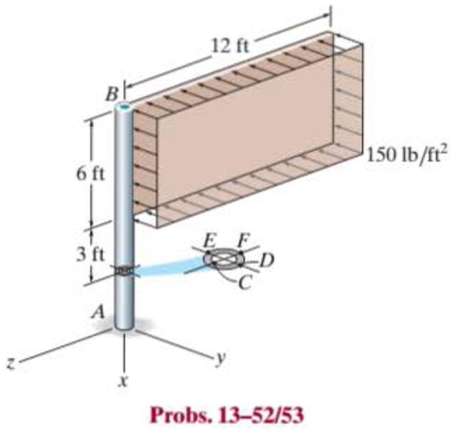
Chapter 13.2, Problem 52P
The uniform sign has a weight of 1500 lb and is supported by the pipe AB, which has an inner radius of 2.75 in. and an outer radius of 3.00 in. If the face of the sign is subjected to a uniform wind pressure of p = 150 lb/ft2, determine the state of stress at points C and D. Show the results on a differential volume clement located at each of these points. Neglect the thickness of the sign, and assume that it is supported along the outside edge of the pipe.
Expert Solution & Answer
Want to see the full answer?
Check out a sample textbook solution
Students have asked these similar questions
Air pressure in the cylinder is increased by exerting forces P = 2 kN on the two pistons, each having a radius of 45 mm. If the cylinder has a wall thickness of 2 mm, determine the state of stress in the wall of the cylinder.
The bent shaft is fixed in the wall at A. If a force F is applied at B (the force is acting on the
plane parallel to the x-o-y plane). Take F = 54 N and 0 = 45°.
1. Determine the internal forces acting on the section containing points D and E
2. Determine the normal stress component acting at point E
3. Determine the shear stress component developed at point E
4. Draw the state of stress on a volume element (stress element) located at point E
5. Determine the principal stresses acting at point E by constructing Mohr's circle
A
150 mm
E
200 mm
30 mm
75 mm
B
F
The solid bar has a diameter of 50 mm. The two forces and the torque Tx are acting at the origin of
the x-y-z coordinate system which is coincident with the centroid of the cross-section of the bar;
the 1800 N force is acting in the y-z plane and torque T is acting about the x-axis. Determine the
state of stress at points A and B, and show the respective stress components acting on differential
elements located at these two points. {30 marks}
200 mm
y 200 mm
B.
1200 N
T= 40 N.m
1800 N
Chapter 13 Solutions
Statics and Mechanics of Materials (5th Edition)
Ch. 13.1 - A spherical gas tank has an inner radius of r =...Ch. 13.1 - A pressurized spherical tank is made of...Ch. 13.1 - The thin-walled cylinder can be supported in one...Ch. 13.1 - Prob. 4PCh. 13.1 - Prob. 5PCh. 13.1 - Determine the maximum force P that can be exerted...Ch. 13.1 - Prob. 7PCh. 13.1 - The steel water pipe has an inner diameter of 12...Ch. 13.1 - The steel water pipe has an inner diameter of 12...Ch. 13.1 - The A-36-steel band is 2 in. wide and is secured...
Ch. 13.1 - The gas pipe line is supported every 20 ft by...Ch. 13.1 - Prob. 12PCh. 13.1 - An A-36-steel hoop has an inner diameter of 23.99...Ch. 13.1 - The ring, having the dimensions shown, is placed...Ch. 13.1 - Prob. 15PCh. 13.1 - Prob. 16PCh. 13.1 - Prob. 17PCh. 13.2 - In each case, determine the internal loadings that...Ch. 13.2 - The internal loadings act on the section. Show the...Ch. 13.2 - Determine the normal stress at comers A and B of...Ch. 13.2 - Determine the state of stress at point A on the...Ch. 13.2 - Determine the state of stress at point A on the...Ch. 13.2 - Determine the magnitude of the load P that will...Ch. 13.2 - Prob. 5FPCh. 13.2 - Determine the state of stress at point A on the...Ch. 13.2 - Determine the state of stress at point A on the...Ch. 13.2 - Determine the state of stress at point A on the...Ch. 13.2 - Determine the shortest distance d to the edge of...Ch. 13.2 - Determine the maximum distance d to the edge of...Ch. 13.2 - The plate has a thickness of 20 mm and the force P...Ch. 13.2 - If the load has a weight of 600 lb, determine the...Ch. 13.2 - The steel bracket is used to connect the ends of...Ch. 13.2 - Prob. 23PCh. 13.2 - The column is built up by gluing the two boards...Ch. 13.2 - Prob. 25PCh. 13.2 - The screw of the clamp exerts a compressive force...Ch. 13.2 - Prob. 27PCh. 13.2 - Prob. 28PCh. 13.2 - The joint is subjected to the force system shown....Ch. 13.2 - Prob. 30PCh. 13.2 - The 12-in.-diameter holt hook is subjected to the...Ch. 13.2 - Prob. 32PCh. 13.2 - Prob. 33PCh. 13.2 - Prob. 34PCh. 13.2 - Prob. 35PCh. 13.2 - The drill is jammed in the wall and is subjected...Ch. 13.2 - The drill is jammed in the wall and is subjected...Ch. 13.2 - The frame supports the distributed load shown....Ch. 13.2 - Prob. 39PCh. 13.2 - The rod has a diameter of 40 mm. If it is...Ch. 13.2 - The rod has a diameter of 40 mm. If it is...Ch. 13.2 - The beveled gear is subjected to the loads shown....Ch. 13.2 - The beveled gear is subjected to the loads shown....Ch. 13.2 - Determine the normal-stress developed at points A...Ch. 13.2 - Sketch the normal-stress distribution acting over...Ch. 13.2 - Prob. 46PCh. 13.2 - The solid rod is subjected to the loading shown....Ch. 13.2 - Prob. 48PCh. 13.2 - Prob. 49PCh. 13.2 - The C-frame is used in a riveting machine. If the...Ch. 13.2 - Prob. 51PCh. 13.2 - The uniform sign has a weight of 1500 lb and is...Ch. 13.2 - The uniform sign has a weight of 1500 lb and is...Ch. 13 - The post has a circular cross section of radius c....Ch. 13 - The 20-kg drum is suspended from the hook mounted...Ch. 13 - The 20-kg drum is suspended from the hook mounted...Ch. 13 - Prob. 4RPCh. 13 - If the cross section of the femur at section aa...Ch. 13 - Prob. 6RPCh. 13 - Prob. 7RPCh. 13 - Prob. 8RP
Knowledge Booster


Learn more about
Need a deep-dive on the concept behind this application? Look no further. Learn more about this topic, mechanical-engineering and related others by exploring similar questions and additional content below.Similar questions
- The sign is subjected to the uniform wind loading. Determine the stress components at points C and D on the 100-mm-diameter supporting post. Show the results on a volume element located at each of these points.arrow_forwardThe solid bar has a diameter of 50 mm. The two forces and the torque Tx are acting at the origin of the x-y-z coordinate system which is coincident with the centroid of the cross-section of the bar; the 1800 N force is acting in the y-z plane and torque Tx is acting about the x-axis. Determine the state of stress at points A and B, and show the respective stress components acting on differential elements located at these two points. 200 mm/ y 200 mm 1200 N Tx = 40 N.m %3D 1800 Narrow_forwardThe steel bracket is used to connect the ends of two cables. If the applied force P = 1.50 kip, determine the maximum normal stress in the bracket. Assume the bracket is a rod having a diameter of 1.5 in.arrow_forward
- The steel water pipe has an inner diameter of 12 in. and a wall thickness of 0.25 in. If the valve A is closed and the water pressure is 300 psi, determine the longitudinal and hoop stress developed in the wall of the pipe at point B. Draw the state of stress on a volume element located on the wall.arrow_forwardDetermine the normal stress and shear stress acting on the inclined plane AB. Solve the problem using the method of equilibrium described in Sec.arrow_forwardDetermine the maximum distance d to the edge of the plate at which the force P can be applied so that it produces no compressive stresses on the plate at section a–a. The plate has a thickness of 20 mm and P acts along thecenterline of this thickness.arrow_forward
- The thin-walled pipe has an inner diameter of 0.5 in. and a thickness of 0.025 in. If it is subjected to an internal pressure of 500 psi and the axial tension and torsional loadings shown, determine the principal stress at a point on the surface of the pipe.arrow_forwardThe 10-mm-diameter steel bolt is surrounded by a bronze sleeve. The outer diameter of this sleeve is 20 mm, and its inner diameter is 10 mm. If the bolt is subjected to a compressive force of P = 20 kN, determine the average normal stress in the steel and the bronze. Est = 200 GPa, Ebr = 100 GPa.arrow_forwardDetermine the normal stress and shear stress acting on the inclined plane AB. Sketch the result on the sectioned element.arrow_forward
- The observation cage C has a weight of 250 kip and through a system of gears, travels upward at constant velocity along the A-36 steel column, which has a height of 200 ft. The column has an outer diameter of 3 ft and is made from steel plate having a thickness of 0.25 in. Neglect the weight of the column, and determine the average normal stress in the column at its base, B, as a function of the cage’s position y. Also, determine the displacement of end A as a function of y.arrow_forwardThe sign is supported by a hollow structural tube of 15 in. outer diameter and 0.5 in. wall thickness. Given the weight and the design 3ft wind loading both acting at the center of the sign, determine the state of stress at points a and 6. Write cach state of stress in the form of a tensor, olserving the r-y-z coordinate system shown, and sketeh the stresses acting on a differential element at each point. s kips 3 kips 3 ft 3ftarrow_forwardAir is pumped into the steel thin-walled pressure vessel at C. If the ends of the vessel are closed using two pistons connected by a rod AB, determine the increase in the diameter of the pressure vessel when the internal gage pressure is 5 MPa. Also, what is the tensile stress in rod AB if it has a diameter of 100 mm? The inner radius of the vessel is 400 mm, and its thickness is 10 mm. Est = 200 GPa and nst = 0.3.arrow_forward
arrow_back_ios
SEE MORE QUESTIONS
arrow_forward_ios
Recommended textbooks for you
 Elements Of ElectromagneticsMechanical EngineeringISBN:9780190698614Author:Sadiku, Matthew N. O.Publisher:Oxford University Press
 Mechanics of Materials (10th Edition)Mechanical EngineeringISBN:9780134319650Author:Russell C. HibbelerPublisher:PEARSON
 Thermodynamics: An Engineering ApproachMechanical EngineeringISBN:9781259822674Author:Yunus A. Cengel Dr., Michael A. BolesPublisher:McGraw-Hill Education
 Control Systems EngineeringMechanical EngineeringISBN:9781118170519Author:Norman S. NisePublisher:WILEY
 Mechanics of Materials (MindTap Course List)Mechanical EngineeringISBN:9781337093347Author:Barry J. Goodno, James M. GerePublisher:Cengage Learning
 Engineering Mechanics: StaticsMechanical EngineeringISBN:9781118807330Author:James L. Meriam, L. G. Kraige, J. N. BoltonPublisher:WILEY
Elements Of Electromagnetics
Mechanical Engineering
ISBN:9780190698614
Author:Sadiku, Matthew N. O.
Publisher:Oxford University Press
Mechanics of Materials (10th Edition)
Mechanical Engineering
ISBN:9780134319650
Author:Russell C. Hibbeler
Publisher:PEARSON
Thermodynamics: An Engineering Approach
Mechanical Engineering
ISBN:9781259822674
Author:Yunus A. Cengel Dr., Michael A. Boles
Publisher:McGraw-Hill Education
Control Systems Engineering
Mechanical Engineering
ISBN:9781118170519
Author:Norman S. Nise
Publisher:WILEY
Mechanics of Materials (MindTap Course List)
Mechanical Engineering
ISBN:9781337093347
Author:Barry J. Goodno, James M. Gere
Publisher:Cengage Learning
Engineering Mechanics: Statics
Mechanical Engineering
ISBN:9781118807330
Author:James L. Meriam, L. G. Kraige, J. N. Bolton
Publisher:WILEY
Everything About COMBINED LOADING in 10 Minutes! Mechanics of Materials; Author: Less Boring Lectures;https://www.youtube.com/watch?v=N-PlI900hSg;License: Standard youtube license