
Statics and Mechanics of Materials (5th Edition)
5th Edition
ISBN: 9780134382593
Author: Russell C. Hibbeler
Publisher: PEARSON
expand_more
expand_more
format_list_bulleted
Concept explainers
Videos
Textbook Question
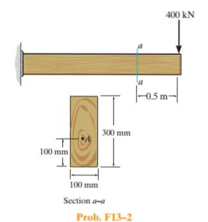
Chapter 13.2, Problem 2FP
Determine the state of stress at point A on the cross section at section a–a of the cantilever beam. Show the results in a differential element at the point.
Expert Solution & Answer
Want to see the full answer?
Check out a sample textbook solution
Students have asked these similar questions
Q What is
Theories of Brittle failure?
Q, what do you mean for each of what's
Coming?
utں وہی رہیں
>
Tyiled
,
Puc
>
Sut, So, KP, Kt, q
When to use this law.
N=
Out Ouc
*
Ouc 1 -Out (01+0₂)
I'm a mechanical engineering student. I don't understand
What is the difference
ductile materials.
between Brittle and
Q2. (30 Marks) For the following figure:
1. Read the tolerances (GD&T) from the figure?
2. Write the Opitz code (5 digits only) for this product?
3. Write few points about point cloud? And how it can be used to inspect the geometry of
products?
4. Draw sketch (free hand) to the top view of the figure below? (())
5. For the symbol below the figure, what does it means? () will jo
الهندسي
08±0.01
A
020±0.01
00.02MAM BM
010±0.01
00.02MAM
ماذا يعني
هذا
B
Q: Find the steady-state response of the system shown in the figure below.
Pulley, mass moment of inertia Jo
寻
k2
00000
For the following data:
Fo sin of
m
00000
uu
x(t)
w
FO
JO
r
m
C
k2
[Rad/s]
[N]
kg-m
[cm]
[Kg]
[N.s/m]
[N/m]
kl
[N/m]
28
58
1.8
13
18
540
540
1080
Chapter 13 Solutions
Statics and Mechanics of Materials (5th Edition)
Ch. 13.1 - A spherical gas tank has an inner radius of r =...Ch. 13.1 - A pressurized spherical tank is made of...Ch. 13.1 - The thin-walled cylinder can be supported in one...Ch. 13.1 - Prob. 4PCh. 13.1 - Prob. 5PCh. 13.1 - Determine the maximum force P that can be exerted...Ch. 13.1 - Prob. 7PCh. 13.1 - The steel water pipe has an inner diameter of 12...Ch. 13.1 - The steel water pipe has an inner diameter of 12...Ch. 13.1 - The A-36-steel band is 2 in. wide and is secured...
Ch. 13.1 - The gas pipe line is supported every 20 ft by...Ch. 13.1 - Prob. 12PCh. 13.1 - An A-36-steel hoop has an inner diameter of 23.99...Ch. 13.1 - The ring, having the dimensions shown, is placed...Ch. 13.1 - Prob. 15PCh. 13.1 - Prob. 16PCh. 13.1 - Prob. 17PCh. 13.2 - In each case, determine the internal loadings that...Ch. 13.2 - The internal loadings act on the section. Show the...Ch. 13.2 - Determine the normal stress at comers A and B of...Ch. 13.2 - Determine the state of stress at point A on the...Ch. 13.2 - Determine the state of stress at point A on the...Ch. 13.2 - Determine the magnitude of the load P that will...Ch. 13.2 - Prob. 5FPCh. 13.2 - Determine the state of stress at point A on the...Ch. 13.2 - Determine the state of stress at point A on the...Ch. 13.2 - Determine the state of stress at point A on the...Ch. 13.2 - Determine the shortest distance d to the edge of...Ch. 13.2 - Determine the maximum distance d to the edge of...Ch. 13.2 - The plate has a thickness of 20 mm and the force P...Ch. 13.2 - If the load has a weight of 600 lb, determine the...Ch. 13.2 - The steel bracket is used to connect the ends of...Ch. 13.2 - Prob. 23PCh. 13.2 - The column is built up by gluing the two boards...Ch. 13.2 - Prob. 25PCh. 13.2 - The screw of the clamp exerts a compressive force...Ch. 13.2 - Prob. 27PCh. 13.2 - Prob. 28PCh. 13.2 - The joint is subjected to the force system shown....Ch. 13.2 - Prob. 30PCh. 13.2 - The 12-in.-diameter holt hook is subjected to the...Ch. 13.2 - Prob. 32PCh. 13.2 - Prob. 33PCh. 13.2 - Prob. 34PCh. 13.2 - Prob. 35PCh. 13.2 - The drill is jammed in the wall and is subjected...Ch. 13.2 - The drill is jammed in the wall and is subjected...Ch. 13.2 - The frame supports the distributed load shown....Ch. 13.2 - Prob. 39PCh. 13.2 - The rod has a diameter of 40 mm. If it is...Ch. 13.2 - The rod has a diameter of 40 mm. If it is...Ch. 13.2 - The beveled gear is subjected to the loads shown....Ch. 13.2 - The beveled gear is subjected to the loads shown....Ch. 13.2 - Determine the normal-stress developed at points A...Ch. 13.2 - Sketch the normal-stress distribution acting over...Ch. 13.2 - Prob. 46PCh. 13.2 - The solid rod is subjected to the loading shown....Ch. 13.2 - Prob. 48PCh. 13.2 - Prob. 49PCh. 13.2 - The C-frame is used in a riveting machine. If the...Ch. 13.2 - Prob. 51PCh. 13.2 - The uniform sign has a weight of 1500 lb and is...Ch. 13.2 - The uniform sign has a weight of 1500 lb and is...Ch. 13 - The post has a circular cross section of radius c....Ch. 13 - The 20-kg drum is suspended from the hook mounted...Ch. 13 - The 20-kg drum is suspended from the hook mounted...Ch. 13 - Prob. 4RPCh. 13 - If the cross section of the femur at section aa...Ch. 13 - Prob. 6RPCh. 13 - Prob. 7RPCh. 13 - Prob. 8RP
Knowledge Booster


Learn more about
Need a deep-dive on the concept behind this application? Look no further. Learn more about this topic, mechanical-engineering and related others by exploring similar questions and additional content below.Similar questions
- Ex. Determine the safety factor for the bracket rod shown below for N = 6 x 10⁷ Cycles. The notch radius at the wall is Y=0.25 cm.. the braket is made from Aluminum 2024, Cold-drawn with σy, 290 MP 441 MPa. L = 10 cm, a = 8 cm, d = 2cm. "Out = d Wall A rod arm a Farrow_forwarddynamically Ex: A rectangular stepped bar is to be loaded in bending. · Determin the fatigue stress concentration factor for a given dimensions. Out = 324 MPa (steel) M d= 1.8 cm 2 D= 1 cm r= 0.25 cmarrow_forwardEx. Create an estimated S-N diagram for an aluminum bar and define its equation . what is the corrected fatigue strength at N = 2 #10 cycles ? Out = 310 MPa, the forged bar is 3.81 cm in N=2107 round. The load is fully reversed torsion.arrow_forward
- and Ex. Create an estimation of S-N diagram for asteel, axially loaded bar and define its equation. How many cycles of life can be expected if the alternating stress is 100 MPa. The bar is 150 min has a hot-rolled finish. The operating temp. is 500 °C. out 600. MPa. The loading will be. pure axial, fully reversed. Square =arrow_forwardCreate an estimation of S-N diagram for asteet, axially loaded bar and define its equation. How many cycles of life can be expected if the alternating stress is 100 MPa. The bar is 150 mm has 9 The loading will be. pure axial, fully reversed. hot-rolled finish. The operating temp. is 500 °C. Out = 600 MPa. Square andarrow_forwardEx. Repeat Ex. in page (24), with fluctuating load as shown below. By = 462 M2, Out = 552 MPa. Find the safety factor (NF) using Modified - Goodman, Gerber, and soderberg criterias F(N) 400 100 timearrow_forward
- ut Ex. The cantilever beam shown is, made from steel with σ = 552 MPa is subjected to fully reversed load. Neglect shear stress q :10 cycles effect, estimate wheather the beam is safe or not safe at N= los The beam is machined surface and the operating temp. is 100c. D 764 L= 10cm L D= 1.3 Cm d = 1 cm b= 1 cm momend diagram -FLarrow_forwardEx. Design to Carry a Cylindrical thin pressure vessel with hemispherical ends for infinite life. Find the appropriate, thickness (t) of the vessel a sinusoidal pressure varied from (0) to (1 MPa). the vessel is made from steel 1030 hotrolled with out = 467.MP¬ and the operating temperature is 300 °C. The diameter of the cylinder D= 0.3 m . Using safety factor N = 2.arrow_forwardEx. Create an estimated S-N diagram for an aluminum bar and define its equation what is the corrected fatigue strength at 7 N = 2 * 10 cycles ? Out = 310 MPa, the forged bar is 3.81 cm in round. The load is fully reversed torsion.arrow_forward
- 1 Estimate the factor of safety fora ductile materail having by = 100 MPa, with the state of stress shown in the element. 30 MPa 12MPA zo M R HP. 1 12MP 30 MPa 20 MPa x '12 MPaarrow_forwardEx. Find the stress concentration factor of grooved shafts that loaded as shown , take 2=2, f = 0.15 j= T тв d a- _b_ _C-arrow_forwardEx. Determine the safety factors for the bracket rod based on the distortion "energy theory and max. shear theory both Given: L= 6 in held 47000 Psi and material is ductile. a = 8 in d = 1.5 in F = 7000-16 arm し Tod F a darrow_forward
arrow_back_ios
SEE MORE QUESTIONS
arrow_forward_ios
Recommended textbooks for you
 Elements Of ElectromagneticsMechanical EngineeringISBN:9780190698614Author:Sadiku, Matthew N. O.Publisher:Oxford University Press
 Mechanics of Materials (10th Edition)Mechanical EngineeringISBN:9780134319650Author:Russell C. HibbelerPublisher:PEARSON
 Thermodynamics: An Engineering ApproachMechanical EngineeringISBN:9781259822674Author:Yunus A. Cengel Dr., Michael A. BolesPublisher:McGraw-Hill Education
 Control Systems EngineeringMechanical EngineeringISBN:9781118170519Author:Norman S. NisePublisher:WILEY
 Mechanics of Materials (MindTap Course List)Mechanical EngineeringISBN:9781337093347Author:Barry J. Goodno, James M. GerePublisher:Cengage Learning
 Engineering Mechanics: StaticsMechanical EngineeringISBN:9781118807330Author:James L. Meriam, L. G. Kraige, J. N. BoltonPublisher:WILEY
Elements Of Electromagnetics
Mechanical Engineering
ISBN:9780190698614
Author:Sadiku, Matthew N. O.
Publisher:Oxford University Press
Mechanics of Materials (10th Edition)
Mechanical Engineering
ISBN:9780134319650
Author:Russell C. Hibbeler
Publisher:PEARSON
Thermodynamics: An Engineering Approach
Mechanical Engineering
ISBN:9781259822674
Author:Yunus A. Cengel Dr., Michael A. Boles
Publisher:McGraw-Hill Education
Control Systems Engineering
Mechanical Engineering
ISBN:9781118170519
Author:Norman S. Nise
Publisher:WILEY
Mechanics of Materials (MindTap Course List)
Mechanical Engineering
ISBN:9781337093347
Author:Barry J. Goodno, James M. Gere
Publisher:Cengage Learning
Engineering Mechanics: Statics
Mechanical Engineering
ISBN:9781118807330
Author:James L. Meriam, L. G. Kraige, J. N. Bolton
Publisher:WILEY
Everything About COMBINED LOADING in 10 Minutes! Mechanics of Materials; Author: Less Boring Lectures;https://www.youtube.com/watch?v=N-PlI900hSg;License: Standard youtube license