
Statics and Mechanics of Materials (5th Edition)
5th Edition
ISBN: 9780134382593
Author: Russell C. Hibbeler
Publisher: PEARSON
expand_more
expand_more
format_list_bulleted
Concept explainers
Videos
Textbook Question
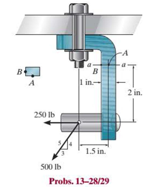
Chapter 13.2, Problem 29P
The joint is subjected to the force system shown. Determine the state of stress at points A and B, and sketch the results on differential elements located at these points. The member has a rectangular cross-sectional area of width 0.5 in. and thickness 1 in.
Expert Solution & Answer
Want to see the full answer?
Check out a sample textbook solution
Students have asked these similar questions
I need answer with diagram and not from AI
One
-1/x²-10.5x+1Z
84.5
11
2x2 +212 +382
2
2
-23.500
81
4th Year
24. (i) Derive a mathematical model for the mechanical system represented below, where the input
Automation and Control
is the Force F, and the output is the displacement x.
(ii)Determine the general transfer function of the system given that the input is an
impulsive force of 10N and the following constants
(iii\Determine the output as a F(s)
(iii) What is the output x as a function of time?
EX
Rnd
0
COM
7
4
Ran# Ra
25 (N/m)
5 kg
30 (N.s/m)
Ans(i) ref notes
2
2
s² + 6s+5
25. A control system has a forward path transfer function of
(111)
(iii) x(t) = 0.5(e-t-e-5t)
2
and a negative feedback loop
four
S+2
with a transfer function 4. What will be the (time) response of the system to a unit step input?
Ans: 0.2(1-e-10)
10
26. A control system has a forward path transfer function of and a negative feedback loop
S+3
with a transfer function 5. What will be the (time) response of the system to a (a) unit impulsive
input? (b) a…
four
One
-H
=
2x2 +212 +382
2
x² -23.5x + x37
84
x -10.5x+h
84.5
Automation and Control
4th Year
24. (i) Derive a mathematical model for the mechanical system represented below, where the input
is the Force F, and the output is the displacement x.
(ii)Determine the general transfer function of the system given that the input is an
impulsive force of 10N and the following constants
(iii\Determine the output as a F(s)
(iii) What is the output x as a function of time?
25 (N/m)
F
5 kg
30 (N.s/m)
2
Ans(i) ref notes
(iii)
(iii) x(t) = 0.5(e-t-e-st)
2
and a negative feedback loop
S+2
s² + 6s+5
25. A control system has a forward path transfer function of
with a transfer function 4. What will be the (time) response of the system to a unit step input?
CON
4
1
Rnd
Rane R
0
EL SALVADOR
Ans: 0.2(1-e-10)
10
s+3
and a negative feedback loop
26. A control system has a forward path transfer function of
with a transfer function 5. What will be the (time) response of the system to a (a) unit impulsive…
Chapter 13 Solutions
Statics and Mechanics of Materials (5th Edition)
Ch. 13.1 - A spherical gas tank has an inner radius of r =...Ch. 13.1 - A pressurized spherical tank is made of...Ch. 13.1 - The thin-walled cylinder can be supported in one...Ch. 13.1 - Prob. 4PCh. 13.1 - Prob. 5PCh. 13.1 - Determine the maximum force P that can be exerted...Ch. 13.1 - Prob. 7PCh. 13.1 - The steel water pipe has an inner diameter of 12...Ch. 13.1 - The steel water pipe has an inner diameter of 12...Ch. 13.1 - The A-36-steel band is 2 in. wide and is secured...
Ch. 13.1 - The gas pipe line is supported every 20 ft by...Ch. 13.1 - Prob. 12PCh. 13.1 - An A-36-steel hoop has an inner diameter of 23.99...Ch. 13.1 - The ring, having the dimensions shown, is placed...Ch. 13.1 - Prob. 15PCh. 13.1 - Prob. 16PCh. 13.1 - Prob. 17PCh. 13.2 - In each case, determine the internal loadings that...Ch. 13.2 - The internal loadings act on the section. Show the...Ch. 13.2 - Determine the normal stress at comers A and B of...Ch. 13.2 - Determine the state of stress at point A on the...Ch. 13.2 - Determine the state of stress at point A on the...Ch. 13.2 - Determine the magnitude of the load P that will...Ch. 13.2 - Prob. 5FPCh. 13.2 - Determine the state of stress at point A on the...Ch. 13.2 - Determine the state of stress at point A on the...Ch. 13.2 - Determine the state of stress at point A on the...Ch. 13.2 - Determine the shortest distance d to the edge of...Ch. 13.2 - Determine the maximum distance d to the edge of...Ch. 13.2 - The plate has a thickness of 20 mm and the force P...Ch. 13.2 - If the load has a weight of 600 lb, determine the...Ch. 13.2 - The steel bracket is used to connect the ends of...Ch. 13.2 - Prob. 23PCh. 13.2 - The column is built up by gluing the two boards...Ch. 13.2 - Prob. 25PCh. 13.2 - The screw of the clamp exerts a compressive force...Ch. 13.2 - Prob. 27PCh. 13.2 - Prob. 28PCh. 13.2 - The joint is subjected to the force system shown....Ch. 13.2 - Prob. 30PCh. 13.2 - The 12-in.-diameter holt hook is subjected to the...Ch. 13.2 - Prob. 32PCh. 13.2 - Prob. 33PCh. 13.2 - Prob. 34PCh. 13.2 - Prob. 35PCh. 13.2 - The drill is jammed in the wall and is subjected...Ch. 13.2 - The drill is jammed in the wall and is subjected...Ch. 13.2 - The frame supports the distributed load shown....Ch. 13.2 - Prob. 39PCh. 13.2 - The rod has a diameter of 40 mm. If it is...Ch. 13.2 - The rod has a diameter of 40 mm. If it is...Ch. 13.2 - The beveled gear is subjected to the loads shown....Ch. 13.2 - The beveled gear is subjected to the loads shown....Ch. 13.2 - Determine the normal-stress developed at points A...Ch. 13.2 - Sketch the normal-stress distribution acting over...Ch. 13.2 - Prob. 46PCh. 13.2 - The solid rod is subjected to the loading shown....Ch. 13.2 - Prob. 48PCh. 13.2 - Prob. 49PCh. 13.2 - The C-frame is used in a riveting machine. If the...Ch. 13.2 - Prob. 51PCh. 13.2 - The uniform sign has a weight of 1500 lb and is...Ch. 13.2 - The uniform sign has a weight of 1500 lb and is...Ch. 13 - The post has a circular cross section of radius c....Ch. 13 - The 20-kg drum is suspended from the hook mounted...Ch. 13 - The 20-kg drum is suspended from the hook mounted...Ch. 13 - Prob. 4RPCh. 13 - If the cross section of the femur at section aa...Ch. 13 - Prob. 6RPCh. 13 - Prob. 7RPCh. 13 - Prob. 8RP
Knowledge Booster


Learn more about
Need a deep-dive on the concept behind this application? Look no further. Learn more about this topic, mechanical-engineering and related others by exploring similar questions and additional content below.Similar questions
- find the temperature distribution of the beam shown below, take &=o.!! and L-1m- of C" loko -10C" 30 со h2 5 Kwlm²-ko T = 250° q=30twarrow_forwardQ1/Create an estimated (S-N) diagram and define its equation for an axial fully reversed loaded steel bar. Its cross section shown in figure (1). Determine the life in cycle that can be expected if the alternating stress is (127Mpa). The bar surface finch is hot rolled. The operating temperature is (506 Co) and (du-577 Mpa). 120 mm. 4arrow_forwardQ4/ Find using a proper design theory the safety factor (N) based on point A for the circular cantilever rod of a diameter (94 mm) shown in figure 3. Knowing that the rod is made of Stainless Steel Type 304-cold rolled, Which is subjected to a force (F= 6.4 kN) inclined with y-axis by 0-72° and to a torque (T= 265π N. m). Fig.3 L1=3.2 cm L2= 3.6 cm F Z Y X (15 Marks) Q5/ Create an estimated S-N diagram and define its equation for an aluminum rectangular bar, shown in figure 4 below, with a (out=342Mpa). The bar is loaded in a fully reversed bending and the bar radius is 12 mm. Determine also the corrected fatigue strength at (N=2.3* 107 cycles). Knowing that the bar surface finch is ground, the operating temperature is 155 C°, and Take a 99.99% reliability factor. Fig. 4 h=5.6 cm Head of the Department: Dr. Deyaa Hassan Jawad Al-Jashami b=4 cm *** Best of Luck *** (15 Marks) Examiner: Ass. Lect. Ahmed A. Tomanarrow_forward
- University of Babylon Collage of Engineering\Al-Musayab Department of Automobile Engineering Under Grad/Third stage Notes: 1-Attempt Four Questions. 2- Q4 Must be Answered 3-Assume any missing data. 4 تسلم الأسئلة بعد الامتحان مع الدفتر Subject: Mechanical Element Design I Date: 2022\01\25 2022-2023 Time: Three Hours Course 1 Attempt 1 Q1/ Design a thin cylindrical pressure tank (pressure vessel) with hemispherical ends to the automotive industry, shown in figure I below. Design for an infinite life by finding the appropriate thickness of the vessel to carry a sinusoidal pressure varied from {(-0.1) to (6) Mpa}. The vessel is made from Stainless Steel Alloy-Type 316 sheet annealed. The operating temperature is 80 C° and the dimeter of the cylinder is 36 cm. use a safety factor of 1.8. Fig. 1 (15 Marks) Q2/ Answer the following: 1- Derive the design equation for the direct evaluation of the diameter of a shaft to a desired fatigue safety factor, if the shaft subjected to both fluctuated…arrow_forwardwhat is the scientific interpetation of all of what comes: 1- axial loading 2- Direct shear loading 3- Torsional loading 4. Bending load 4- Explain it in detail and how to use it to solve mechanical design Problemsarrow_forwardConsider the magnetic levitation system shown in Figure 1. An electromagnet is located at the upper part of the experimental system. Using the electromagnetic force f, you want to suspend the iron ball. Assume that the state variables are x₁ = x, x2 = x, and x3 =i. The electromagnet has an inductance L = 0.508H and a resistance R = 23.2. Use a Taylor series approximation for the electromagnetic force. The current is i₁ = 10 + i, where I = 1.06A is the operating point and i is the variable. The mass m is equal to 1.75kg. The gap is x = x + x, where x = 4.36mm is the operating point and x is the variable. The electromagnetic force is f = k(₁₁/xg)², where k = 2.9 × 10⁻⁴ Nm²/A². a) Determine the state matrix differential equation. b) Find the equivalent transfer function X(s)/V(s). Note: v(t) (+ Electromagnet i₁(t) Iron ball Force f(t) x(t) mg Gap sensor Figure 1 The magnetic levitation system is essentially unworkable. Hence, feedback control is crucial. A standard induction probe of the…arrow_forward
- Q3/ a steel plate shown in figure (3): Su689 Mpa, reliability is 90%, factor of safety is 2, the size factor is 0.87. machined surface. Determine the plate thickness (t) for infinite life. Note: All dimensions are in mm. P= ± 50 kN 100 Fig. 3 177 5r P = ± 50 kN 540 50arrow_forwardQ2/A cantilever beam, shown in figure (2), is to be made from [Wrought-Aluminum Alloys- 3003- cold rolled]. If the desired design factor is (N-2.5), (P-4kN), and (F-6kN). Using a suitable failure theory, find the appropriate beam thickness h. T D=15cm d=100mm r=20mm L= 25 cm Karrow_forwardSolve full assignment with steps pleasearrow_forward
- Please solvearrow_forwardFlow between parallel plates h Y Q water flow Perforated plate inflow inside u+ou You have a channel system in which the water leaky-wall BC flows through and is bounded with two perforated plates at the bottom and the top. Consider steady, incompressible, laminar flow between two infinite parallel horizontal plates as shown in the figure. h is the half of the hydraulic aperture (m). At the top and the bottom, perforated blocks are connected on both side plates a liquid inflows and mixes into the main water flow channel system and you would like to evaluate the total volumetric flow rate Q (m³ s¹). бл 0- 2 -by Perforated plate inflow inside leaky-wall BC P+5P The flow is in the x-direction, and there is no velocity component in either the y-or z-direction (i.e., v = 0 and w=0). In steady-state conditions applying the simple form of the Navier-Stokes equations (or similar to Poiseuille's law), along with the assumptions that v = 0, w = 0, and u = u(y) yields 88 др μ др др =-pg, =0 Oz.…arrow_forwardA pump is used to deliver water from a reservoir to a large tank for a flow rate of 1310 L/s at 20 °C. The connecting pipe connects the reservoir at B with a square-edged entrance.arrow_forward
arrow_back_ios
SEE MORE QUESTIONS
arrow_forward_ios
Recommended textbooks for you
 Elements Of ElectromagneticsMechanical EngineeringISBN:9780190698614Author:Sadiku, Matthew N. O.Publisher:Oxford University Press
 Mechanics of Materials (10th Edition)Mechanical EngineeringISBN:9780134319650Author:Russell C. HibbelerPublisher:PEARSON
 Thermodynamics: An Engineering ApproachMechanical EngineeringISBN:9781259822674Author:Yunus A. Cengel Dr., Michael A. BolesPublisher:McGraw-Hill Education
 Control Systems EngineeringMechanical EngineeringISBN:9781118170519Author:Norman S. NisePublisher:WILEY
 Mechanics of Materials (MindTap Course List)Mechanical EngineeringISBN:9781337093347Author:Barry J. Goodno, James M. GerePublisher:Cengage Learning
 Engineering Mechanics: StaticsMechanical EngineeringISBN:9781118807330Author:James L. Meriam, L. G. Kraige, J. N. BoltonPublisher:WILEY
Elements Of Electromagnetics
Mechanical Engineering
ISBN:9780190698614
Author:Sadiku, Matthew N. O.
Publisher:Oxford University Press
Mechanics of Materials (10th Edition)
Mechanical Engineering
ISBN:9780134319650
Author:Russell C. Hibbeler
Publisher:PEARSON
Thermodynamics: An Engineering Approach
Mechanical Engineering
ISBN:9781259822674
Author:Yunus A. Cengel Dr., Michael A. Boles
Publisher:McGraw-Hill Education
Control Systems Engineering
Mechanical Engineering
ISBN:9781118170519
Author:Norman S. Nise
Publisher:WILEY
Mechanics of Materials (MindTap Course List)
Mechanical Engineering
ISBN:9781337093347
Author:Barry J. Goodno, James M. Gere
Publisher:Cengage Learning
Engineering Mechanics: Statics
Mechanical Engineering
ISBN:9781118807330
Author:James L. Meriam, L. G. Kraige, J. N. Bolton
Publisher:WILEY
Everything About COMBINED LOADING in 10 Minutes! Mechanics of Materials; Author: Less Boring Lectures;https://www.youtube.com/watch?v=N-PlI900hSg;License: Standard youtube license