Statics and Mechanics of Materials (5th Edition)
5th Edition
ISBN: 9780134382593
Author: Russell C. Hibbeler
Publisher: PEARSON
expand_more
expand_more
format_list_bulleted
Concept explainers
Textbook Question
Chapter 13.1, Problem 8P
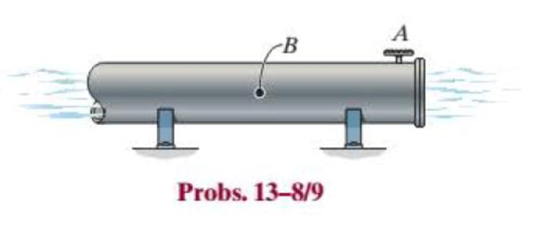
The steel water pipe has an inner diameter of 12 in. and a wall thickness of 0.25 in. If the valve A is opened and the flowing water has a pressure of 250 psi as it passes point B, determine the longitudinal and hoop stress developed in the wall of the pipe at point B.

Expert Solution & Answer
Want to see the full answer?
Check out a sample textbook solution
Students have asked these similar questions
Please solve
Flow between
parallel plates
h
Y
Q
water flow
Perforated plate
inflow inside
u+ou
You have a channel system in which the water
leaky-wall BC flows through and is bounded with two
perforated plates at the bottom and the top.
Consider steady, incompressible, laminar flow
between two infinite parallel horizontal plates as
shown in the figure. h is the half of the hydraulic
aperture (m). At the top and the bottom,
perforated blocks are connected on both side
plates a liquid inflows and mixes into the main
water flow channel system and you would like to
evaluate the total volumetric flow rate Q (m³ s¹).
бл
0-
2
-by
Perforated plate
inflow inside
leaky-wall BC
P+5P
The flow is in the x-direction, and there is no velocity component in either the y-or z-direction (i.e., v = 0
and w=0). In steady-state conditions applying the simple form of the Navier-Stokes equations (or similar
to Poiseuille's law), along with the assumptions that v = 0, w = 0, and u = u(y) yields
88
др
μ
др
др
=-pg,
=0
Oz.…
A pump is used to deliver water from a reservoir to a large tank for a flow rate of 1310 L/s at 20 °C. The connecting pipe connects the reservoir at B with a square-edged entrance.
Chapter 13 Solutions
Statics and Mechanics of Materials (5th Edition)
Ch. 13.1 - A spherical gas tank has an inner radius of r =...Ch. 13.1 - A pressurized spherical tank is made of...Ch. 13.1 - The thin-walled cylinder can be supported in one...Ch. 13.1 - Prob. 4PCh. 13.1 - Prob. 5PCh. 13.1 - Determine the maximum force P that can be exerted...Ch. 13.1 - Prob. 7PCh. 13.1 - The steel water pipe has an inner diameter of 12...Ch. 13.1 - The steel water pipe has an inner diameter of 12...Ch. 13.1 - The A-36-steel band is 2 in. wide and is secured...
Ch. 13.1 - The gas pipe line is supported every 20 ft by...Ch. 13.1 - Prob. 12PCh. 13.1 - An A-36-steel hoop has an inner diameter of 23.99...Ch. 13.1 - The ring, having the dimensions shown, is placed...Ch. 13.1 - Prob. 15PCh. 13.1 - Prob. 16PCh. 13.1 - Prob. 17PCh. 13.2 - In each case, determine the internal loadings that...Ch. 13.2 - The internal loadings act on the section. Show the...Ch. 13.2 - Determine the normal stress at comers A and B of...Ch. 13.2 - Determine the state of stress at point A on the...Ch. 13.2 - Determine the state of stress at point A on the...Ch. 13.2 - Determine the magnitude of the load P that will...Ch. 13.2 - Prob. 5FPCh. 13.2 - Determine the state of stress at point A on the...Ch. 13.2 - Determine the state of stress at point A on the...Ch. 13.2 - Determine the state of stress at point A on the...Ch. 13.2 - Determine the shortest distance d to the edge of...Ch. 13.2 - Determine the maximum distance d to the edge of...Ch. 13.2 - The plate has a thickness of 20 mm and the force P...Ch. 13.2 - If the load has a weight of 600 lb, determine the...Ch. 13.2 - The steel bracket is used to connect the ends of...Ch. 13.2 - Prob. 23PCh. 13.2 - The column is built up by gluing the two boards...Ch. 13.2 - Prob. 25PCh. 13.2 - The screw of the clamp exerts a compressive force...Ch. 13.2 - Prob. 27PCh. 13.2 - Prob. 28PCh. 13.2 - The joint is subjected to the force system shown....Ch. 13.2 - Prob. 30PCh. 13.2 - The 12-in.-diameter holt hook is subjected to the...Ch. 13.2 - Prob. 32PCh. 13.2 - Prob. 33PCh. 13.2 - Prob. 34PCh. 13.2 - Prob. 35PCh. 13.2 - The drill is jammed in the wall and is subjected...Ch. 13.2 - The drill is jammed in the wall and is subjected...Ch. 13.2 - The frame supports the distributed load shown....Ch. 13.2 - Prob. 39PCh. 13.2 - The rod has a diameter of 40 mm. If it is...Ch. 13.2 - The rod has a diameter of 40 mm. If it is...Ch. 13.2 - The beveled gear is subjected to the loads shown....Ch. 13.2 - The beveled gear is subjected to the loads shown....Ch. 13.2 - Determine the normal-stress developed at points A...Ch. 13.2 - Sketch the normal-stress distribution acting over...Ch. 13.2 - Prob. 46PCh. 13.2 - The solid rod is subjected to the loading shown....Ch. 13.2 - Prob. 48PCh. 13.2 - Prob. 49PCh. 13.2 - The C-frame is used in a riveting machine. If the...Ch. 13.2 - Prob. 51PCh. 13.2 - The uniform sign has a weight of 1500 lb and is...Ch. 13.2 - The uniform sign has a weight of 1500 lb and is...Ch. 13 - The post has a circular cross section of radius c....Ch. 13 - The 20-kg drum is suspended from the hook mounted...Ch. 13 - The 20-kg drum is suspended from the hook mounted...Ch. 13 - Prob. 4RPCh. 13 - If the cross section of the femur at section aa...Ch. 13 - Prob. 6RPCh. 13 - Prob. 7RPCh. 13 - Prob. 8RP
Knowledge Booster
Learn more about
Need a deep-dive on the concept behind this application? Look no further. Learn more about this topic, mechanical-engineering and related others by exploring similar questions and additional content below.Similar questions
- 7.5 (A/B). Fig. 7.18 shows the cross-section of a beam which carries a shear force of 20 kN. Plot a graph to scale which shows the distribution of shear stress due to bending across the cross-section. [I.Mech.E.] [21.7, 5.2, 5.23 MN/m².] 12 mm 75 mm 40mm -50mm-arrow_forwardThe ramp ABCD is supported at the corners by cables at C and D. If the tension exerted in each of the cables is 950 N, determine the moment about A of the force exerted by : a) The cable at C b) The cable at D. D 0.7 m E 3.3 m F B G H A 2.3 m 3 m C 0.7 m 1 m xarrow_forwardThe assembly is made of slender rods that have a mass per unitlength of 3 kg/m. Determine the mass moment of inertia and radius of gyration ofthe assembly about an axis perpendicular to the page and passing through point O.arrow_forward
- At a given instant the top B of the ladder has an acceleration aB = 2 ft/s^2 and a velocity of vB = 4 ft/s, both acting downward. Determine the velocity and acceleration of the bottom A of the ladder, and the ladder's angular acceleration at this instant.arrow_forward2. A small radiant source 4₁ emits diffusely with an intensity I₁= 1.2 × 10⁵ W/m². sr. The radiation detector 42 is aligned normal to the source at a distance of Lo = 0.2 m. An opaque screen is positioned midway between A1 and A2 to prevent radiation from the source reaching the detector. The small surface Am is a perfectly diffuse mirror that permits radiation emitted from the source to be reflected into the detector. y₁ = 0.1 m- Opaque screen A₂ = A1 Am = 2A1 A₁ = 1 x 10⁴ m² 0 x = 0.1 m x+ L₁ = 0.2 m (a) Calculate the radiant power incident on Am due to emission from the source A1, 91→m(W). (b) Assuming that the radiant power, 91→m, is perfectly and diffusely reflected, calculate the intensity leaving Am, Im (W/m². sr). (c) Calculate the radiant power incident on 42 due to the reflected radiation leaving Am, 9m→2(μW).arrow_forward1. Consider a small surface of area A₁ = 10ª m², which emits diffusely with a total, hemispherical emissive power of E₁ = 5 × 10⁴ W/m². n₂ 8₁₂ = 30° A₂ 72 = 0.5 m 0₁ = 60° (a) At what rate is this emission intercepted by a small surface of area 42 = 5 x 10⁴m², which is oriented as shown? (b) What is the irradiation G₂ on 42?arrow_forward
- 3. The energy flux associated with solar radiation incident on the outer surface of the earth's atmosphere has been accurately measured and is known to be 1368 W/m². The diameters of the sun and earth are 1.39 × 10° and 1.27 × 10⁷m, respectively, and the distance between the sun and the earth is 1.5 × 10¹¹ m. (a) What is the emissive power of the sun? (b) Approximating the sun's surface as black, what is its temperature? (c) At what wavelength is the spectral emissive power of the sun a maximum? (d) Assuming the earth's surface to be black and the sun to be the only source of energy for the earth, estimate the earth's surface temperature.arrow_forwardDetermine the angular momentum Ho of the 8-lb particle about point O.arrow_forward5. Prove if the following trusses are determinate or not, and identify the Zero-force members by drawing a red line on them. B P Σ E F ст 5 I K Jarrow_forward
- 2m 7. Using the method of section, solve for BC, CH, and FH. 3KN 2.5m 2KH 2.5m 2.5marrow_forward4. Determine the support reactions at point A and B. A 100 lb/ft 300 lb B 4' — 4' → 2' 2'arrow_forwardWhile you’re inspecting the different rotating systems in the department, you notice some vibrations coming from an old rotor assembly. Determine the balancing masses needed in planes P and Q to dynamically balance the rotor shown below, given that: m1=120g, at radius r1=50mm, and θ1= 90o , m2=60g at radius r2=62.5mm and θ2=0o. The distances are P-1=150mm, 1-2=150mm and 2-Q=150mm, respectively.arrow_forward
arrow_back_ios
SEE MORE QUESTIONS
arrow_forward_ios
Recommended textbooks for you
 Elements Of ElectromagneticsMechanical EngineeringISBN:9780190698614Author:Sadiku, Matthew N. O.Publisher:Oxford University Press
 Mechanics of Materials (10th Edition)Mechanical EngineeringISBN:9780134319650Author:Russell C. HibbelerPublisher:PEARSON
 Thermodynamics: An Engineering ApproachMechanical EngineeringISBN:9781259822674Author:Yunus A. Cengel Dr., Michael A. BolesPublisher:McGraw-Hill Education
 Control Systems EngineeringMechanical EngineeringISBN:9781118170519Author:Norman S. NisePublisher:WILEY
 Mechanics of Materials (MindTap Course List)Mechanical EngineeringISBN:9781337093347Author:Barry J. Goodno, James M. GerePublisher:Cengage Learning
 Engineering Mechanics: StaticsMechanical EngineeringISBN:9781118807330Author:James L. Meriam, L. G. Kraige, J. N. BoltonPublisher:WILEY

Elements Of Electromagnetics
Mechanical Engineering
ISBN:9780190698614
Author:Sadiku, Matthew N. O.
Publisher:Oxford University Press

Mechanics of Materials (10th Edition)
Mechanical Engineering
ISBN:9780134319650
Author:Russell C. Hibbeler
Publisher:PEARSON

Thermodynamics: An Engineering Approach
Mechanical Engineering
ISBN:9781259822674
Author:Yunus A. Cengel Dr., Michael A. Boles
Publisher:McGraw-Hill Education

Control Systems Engineering
Mechanical Engineering
ISBN:9781118170519
Author:Norman S. Nise
Publisher:WILEY

Mechanics of Materials (MindTap Course List)
Mechanical Engineering
ISBN:9781337093347
Author:Barry J. Goodno, James M. Gere
Publisher:Cengage Learning

Engineering Mechanics: Statics
Mechanical Engineering
ISBN:9781118807330
Author:James L. Meriam, L. G. Kraige, J. N. Bolton
Publisher:WILEY
Pressure Vessels Introduction; Author: Engineering and Design Solutions;https://www.youtube.com/watch?v=Z1J97IpFc2k;License: Standard youtube license