
Statics and Mechanics of Materials (5th Edition)
5th Edition
ISBN: 9780134382593
Author: Russell C. Hibbeler
Publisher: PEARSON
expand_more
expand_more
format_list_bulleted
Concept explainers
Videos
Textbook Question
Chapter 13.2, Problem 21P
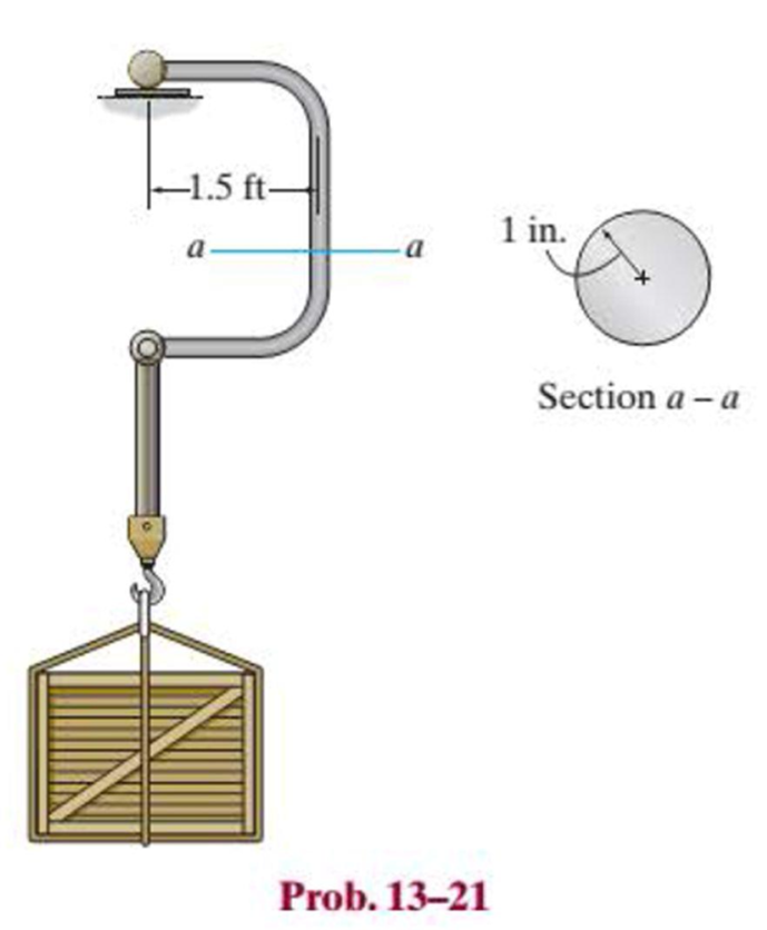
If the load has a weight of 600 lb, determine the maximum normal stress on the cross section of the supporting member at section a–a. Also, plot the normal-stress distribution over the cross section.
Expert Solution & Answer
Want to see the full answer?
Check out a sample textbook solution
Students have asked these similar questions
If the load has a weight of 600 lb, determine the maximum normal stress on the cross section of the supporting member at section a–a. Also, plot the normalstress distribution over the cross section.
The block is subjected to the eccentric load shown. Sketch the normal-stress distribution acting over the cross section at section a–a. Neglect the weight of the block.
Determine the shear stress at point B on the web of the cantilevered strut at section a–a.
Chapter 13 Solutions
Statics and Mechanics of Materials (5th Edition)
Ch. 13.1 - A spherical gas tank has an inner radius of r =...Ch. 13.1 - A pressurized spherical tank is made of...Ch. 13.1 - The thin-walled cylinder can be supported in one...Ch. 13.1 - Prob. 4PCh. 13.1 - Prob. 5PCh. 13.1 - Determine the maximum force P that can be exerted...Ch. 13.1 - Prob. 7PCh. 13.1 - The steel water pipe has an inner diameter of 12...Ch. 13.1 - The steel water pipe has an inner diameter of 12...Ch. 13.1 - The A-36-steel band is 2 in. wide and is secured...
Ch. 13.1 - The gas pipe line is supported every 20 ft by...Ch. 13.1 - Prob. 12PCh. 13.1 - An A-36-steel hoop has an inner diameter of 23.99...Ch. 13.1 - The ring, having the dimensions shown, is placed...Ch. 13.1 - Prob. 15PCh. 13.1 - Prob. 16PCh. 13.1 - Prob. 17PCh. 13.2 - In each case, determine the internal loadings that...Ch. 13.2 - The internal loadings act on the section. Show the...Ch. 13.2 - Determine the normal stress at comers A and B of...Ch. 13.2 - Determine the state of stress at point A on the...Ch. 13.2 - Determine the state of stress at point A on the...Ch. 13.2 - Determine the magnitude of the load P that will...Ch. 13.2 - Prob. 5FPCh. 13.2 - Determine the state of stress at point A on the...Ch. 13.2 - Determine the state of stress at point A on the...Ch. 13.2 - Determine the state of stress at point A on the...Ch. 13.2 - Determine the shortest distance d to the edge of...Ch. 13.2 - Determine the maximum distance d to the edge of...Ch. 13.2 - The plate has a thickness of 20 mm and the force P...Ch. 13.2 - If the load has a weight of 600 lb, determine the...Ch. 13.2 - The steel bracket is used to connect the ends of...Ch. 13.2 - Prob. 23PCh. 13.2 - The column is built up by gluing the two boards...Ch. 13.2 - Prob. 25PCh. 13.2 - The screw of the clamp exerts a compressive force...Ch. 13.2 - Prob. 27PCh. 13.2 - Prob. 28PCh. 13.2 - The joint is subjected to the force system shown....Ch. 13.2 - Prob. 30PCh. 13.2 - The 12-in.-diameter holt hook is subjected to the...Ch. 13.2 - Prob. 32PCh. 13.2 - Prob. 33PCh. 13.2 - Prob. 34PCh. 13.2 - Prob. 35PCh. 13.2 - The drill is jammed in the wall and is subjected...Ch. 13.2 - The drill is jammed in the wall and is subjected...Ch. 13.2 - The frame supports the distributed load shown....Ch. 13.2 - Prob. 39PCh. 13.2 - The rod has a diameter of 40 mm. If it is...Ch. 13.2 - The rod has a diameter of 40 mm. If it is...Ch. 13.2 - The beveled gear is subjected to the loads shown....Ch. 13.2 - The beveled gear is subjected to the loads shown....Ch. 13.2 - Determine the normal-stress developed at points A...Ch. 13.2 - Sketch the normal-stress distribution acting over...Ch. 13.2 - Prob. 46PCh. 13.2 - The solid rod is subjected to the loading shown....Ch. 13.2 - Prob. 48PCh. 13.2 - Prob. 49PCh. 13.2 - The C-frame is used in a riveting machine. If the...Ch. 13.2 - Prob. 51PCh. 13.2 - The uniform sign has a weight of 1500 lb and is...Ch. 13.2 - The uniform sign has a weight of 1500 lb and is...Ch. 13 - The post has a circular cross section of radius c....Ch. 13 - The 20-kg drum is suspended from the hook mounted...Ch. 13 - The 20-kg drum is suspended from the hook mounted...Ch. 13 - Prob. 4RPCh. 13 - If the cross section of the femur at section aa...Ch. 13 - Prob. 6RPCh. 13 - Prob. 7RPCh. 13 - Prob. 8RP
Knowledge Booster


Learn more about
Need a deep-dive on the concept behind this application? Look no further. Learn more about this topic, mechanical-engineering and related others by exploring similar questions and additional content below.Similar questions
- The eye hook has the dimensions shown. If it supports a cable loading of 800 lb, determine the maximum normal stress at section a–a and sketch the stress distribution acting over the cross section. Use the curved-beam formula to calculate the bending stress.arrow_forwardThe screw of the clamp exerts a compressive force of 500 lb on the wood blocks. Determine the maximum normal stress along section a–a. The cross section is rectangular, 0.75 in. by 0.50 in.arrow_forwardThe plate has a thickness of 20 mm and width s = 260 mm. Force P acts along the centerline of this thickness. Determine the maximum distance d at which the force P can be applied so that it produces no compressive stresses on the plate at section a-a.arrow_forward
- The cantilever strut is subjected to the point loads P1 = 1.4 kN and P2 = 2.8 kN. Determine the shear stress at point B on the web of the cantilever strut at section a–a.arrow_forwardX A purse hook is used to hang a handbag from the edge of a table with L = 50 mm. If the cross section at a-a has a diameter of d = 3 mm and the hook is supporting a purse with a mass of 3 kg, determine the normal stress profile. For what value of y (using the coordinates pictured for section a-a) with the normal stress be zero. If it is never zero enter "nde" for "not defined". N -L→ a. a AB C Follow sign convention that tension is positive and compression is negative. Normal stress at point A, σA= MPa Normal stress at point B, σB = MPa Normal stress at point C, σc = MPa y position where normal stress equals zero = mm Section a-a darrow_forwardDetermine the normal stress and shear stress acting on the inclined plane AB. Sketch the result on the sectioned element.arrow_forward
- The solid circular rod has a cross-sectional area of 450 mm2. It is subjected to a uniform axial distributed loading along its length of w = 9 kN/m. Two concentrated loads also act on the rod: P = 5 kN and Q = 7 kN. Determine the normal stress in the rod at x = 0.9 m. Assume a = 0.4 m and b = 1.0 m.arrow_forwardUse Mohr's Circle to determine the maximum shear stress on the element, also using Mohr's Circle determine the maximum normal stress on the element.arrow_forwardThe plate has a thickness of 20 mm and the force P = 3 kN acts along the centerline of this thickness such that d = 150 mm. Plot the distribution of normal stress acting along section a–a.arrow_forward
- The steel bracket is used to connect the ends of two cables. If the applied force P = 1.50 kip, determine the maximum normal stress in the bracket. Assume the bracket is a rod having a diameter of 1.5 in.arrow_forwardThe horizontal force of P = 80 KN acts at the end of the plate. The plate has a thickness of 10 mm and P acts along the centerline of this thickness such that d = 50 mm. Plot the distribution of normal stress acting along section a-a.arrow_forward) If the load has a weight of 600 lb, determine the maximum normal stress developed on the cross section of the supporting member at section a-a. Also, plot the normal stress distribution over the cross section. -1.5 ft- 1 in. 4 Section a-aarrow_forward
arrow_back_ios
SEE MORE QUESTIONS
arrow_forward_ios
Recommended textbooks for you
 Elements Of ElectromagneticsMechanical EngineeringISBN:9780190698614Author:Sadiku, Matthew N. O.Publisher:Oxford University Press
 Mechanics of Materials (10th Edition)Mechanical EngineeringISBN:9780134319650Author:Russell C. HibbelerPublisher:PEARSON
 Thermodynamics: An Engineering ApproachMechanical EngineeringISBN:9781259822674Author:Yunus A. Cengel Dr., Michael A. BolesPublisher:McGraw-Hill Education
 Control Systems EngineeringMechanical EngineeringISBN:9781118170519Author:Norman S. NisePublisher:WILEY
 Mechanics of Materials (MindTap Course List)Mechanical EngineeringISBN:9781337093347Author:Barry J. Goodno, James M. GerePublisher:Cengage Learning
 Engineering Mechanics: StaticsMechanical EngineeringISBN:9781118807330Author:James L. Meriam, L. G. Kraige, J. N. BoltonPublisher:WILEY
Elements Of Electromagnetics
Mechanical Engineering
ISBN:9780190698614
Author:Sadiku, Matthew N. O.
Publisher:Oxford University Press
Mechanics of Materials (10th Edition)
Mechanical Engineering
ISBN:9780134319650
Author:Russell C. Hibbeler
Publisher:PEARSON
Thermodynamics: An Engineering Approach
Mechanical Engineering
ISBN:9781259822674
Author:Yunus A. Cengel Dr., Michael A. Boles
Publisher:McGraw-Hill Education
Control Systems Engineering
Mechanical Engineering
ISBN:9781118170519
Author:Norman S. Nise
Publisher:WILEY
Mechanics of Materials (MindTap Course List)
Mechanical Engineering
ISBN:9781337093347
Author:Barry J. Goodno, James M. Gere
Publisher:Cengage Learning
Engineering Mechanics: Statics
Mechanical Engineering
ISBN:9781118807330
Author:James L. Meriam, L. G. Kraige, J. N. Bolton
Publisher:WILEY
Everything About COMBINED LOADING in 10 Minutes! Mechanics of Materials; Author: Less Boring Lectures;https://www.youtube.com/watch?v=N-PlI900hSg;License: Standard youtube license