
Electronics Fundamentals: Circuits, Devices & Applications
8th Edition
ISBN: 9780135072950
Author: Thomas L. Floyd, David Buchla
Publisher: Prentice Hall
expand_more
expand_more
format_list_bulleted
Concept explainers
Videos
Textbook Question
Chapter 11, Problem 20P
What frequency will produce a total rms current of 500 mA in each circuit of Figure 11-43 with an rms input voltage of 10 V?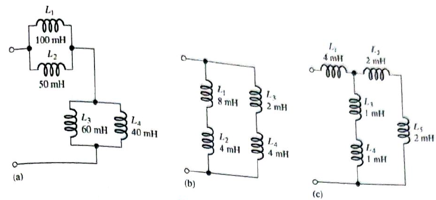
Expert Solution & Answer
Want to see the full answer?
Check out a sample textbook solution
Students have asked these similar questions
Using phone hand
I need expert handwritten solutions
Show handwriting solutions not Ai
Chapter 11 Solutions
Electronics Fundamentals: Circuits, Devices & Applications
Ch. 11 - Lenz’s law states that the amount of voltage...Ch. 11 - An ideal inductor has no winding resistance.Ch. 11 - The total inductance of two parallel inductors is...Ch. 11 - The total inductance of parallel inductors is...Ch. 11 - The time constant of an RL circuit is given by the...Ch. 11 - Prob. 6TFQCh. 11 - Prob. 7TFQCh. 11 - Prob. 8TFQCh. 11 - Prob. 9TFQCh. 11 - Prob. 10TFQ
Ch. 11 - Prob. 1STCh. 11 - Prob. 2STCh. 11 - When the current through an inductor increases,...Ch. 11 - Prob. 4STCh. 11 - Prob. 5STCh. 11 - Prob. 6STCh. 11 - Prob. 7STCh. 11 - Prob. 8STCh. 11 - Prob. 9STCh. 11 - Prob. 10STCh. 11 - Prob. 11STCh. 11 - Prob. 1TSCCh. 11 - Prob. 2TSCCh. 11 - Symptom: The voltmeter 1 reading is 5 V, and the...Ch. 11 - Prob. 4TSCCh. 11 - Prob. 5TSCCh. 11 - Prob. 1PCh. 11 - Prob. 2PCh. 11 - Prob. 3PCh. 11 - A 12 V battery is connected across a coil with a...Ch. 11 - Prob. 5PCh. 11 - The current through a 100 mH coil is changing at a...Ch. 11 - Prob. 7PCh. 11 - Suppose that you require a total inductance of 50...Ch. 11 - Prob. 9PCh. 11 - Prob. 10PCh. 11 - Determine the total inductance of each circuit in...Ch. 11 - Determine the total inductance of each circuit in...Ch. 11 - Prob. 13PCh. 11 - In a series RL circuit, determine how long it...Ch. 11 - Prob. 15PCh. 11 - In Figure 11-45, calculate the current at each of...Ch. 11 - Prob. 17PCh. 11 - Find the total reactance for each circuit in...Ch. 11 - Determine the total rms current in Figure 11-46....Ch. 11 - What frequency will produce a total rms current of...Ch. 11 - Prob. 21PCh. 11 - Determine the time constant for the circuit in...Ch. 11 - Prob. 23PCh. 11 - Prob. 24PCh. 11 - What is the current in the inductor 1.0s after the...Ch. 11 - Prob. 26PCh. 11 - Prob. 27PCh. 11 - Prob. 28PCh. 11 - Prob. 29PCh. 11 - Prob. 30PCh. 11 - Prob. 32P
Knowledge Booster


Learn more about
Need a deep-dive on the concept behind this application? Look no further. Learn more about this topic, electrical-engineering and related others by exploring similar questions and additional content below.Similar questions
- Maul Dulde Questio119 819 PREV NEXT In the lab, you have setup a thermocouple and have used a thermistor along with an ice bath and water at various temperatures (confirmed with the thermistor) up to 100 degrees Celsius for calibration. The calibration data is shown in the table below and the full-scale output range is 0-5 mV. You note that there is scatter in your data; however, you must use a linear curve fit to efficiently process the measurements during an automated temperature measurement process. Question 1 100% Question 2 100% Question 3 100% Question 4 100% Question 5 100% Question 6 100% mV The slope of your linear calibration curve for the thermocouple is 0.0334 °C with an offset of -0.07 mV. Question 7 100% Question 8 100% What is the maximum expected linearity error as a percentage of the full-scale output? Question 9 0% Summary -0.08 Thermocouple Calibration Data Temperature (°C) Voltage (in mV) 0 20 20 40 40 60 60 60 80 96 90 0.587 1.314 1.901 2.528 2.782 100 3.055 LIT…arrow_forwardOnly expert should solve itarrow_forwardWhat is the high cutoff frequency? What is the low cutoff frequency? What is the bandwidth?arrow_forward
- Need handwritten pen and paper solution do not use chatgpt or AI otherwise downvote. An AC motor with impedance Z₁ = 4.2 + j3.6 ohm is supplied from a source of 220 V at 60 Hz. Find: a) pf, P and Q, b) Determine the capacitor required to connect in parallel with the motor so that the power factor is corrected and equal to 0.98 behind.arrow_forwardNeed handwritten pen and paper solution do not use chatgpt or AI otherwise downvote An AC motor with impedance Z₁ = 4.2 + j3.6 ohm is supplied from a source of 220 V at 60 Hz. Find: a) pf, P and Q, b) Determine the capacitor required to connect in parallel with the motor so that the power factor is corrected and equal to 0.98 behind.arrow_forwardFind;- magnitude of line voltages Line currents Verify that th eload is balanced, i.e In = 0arrow_forward
- Don't use ai to answer I will report you answerarrow_forwardDon't use ai to answer I will report you answerarrow_forward(b) Below is a FSM with a 1-bit input A, and a 1-bit output Y. Deter- mine the combined state and output table. Identify the unreachable states, and sketch the state-transition diagram. In your table and diagram, use Os and 1s for the states and next states, not symbols like S0, S1, etc. A D D D CLK S'₁₂ S2 S₁₁ S1 Y S' r So S2 S₁ So resetarrow_forward
- Do by pen and paper not using chatgpt Determine the output current of E1 in the circuit shown in . The voltage drop of the diodes is 0.7 V.arrow_forwardDon't use ai to answer I will report you answerarrow_forwardFor the amplifier shown, if β = 150: Calculate the input impedance at the base. Calculate the input impedance of the stage.arrow_forward
arrow_back_ios
SEE MORE QUESTIONS
arrow_forward_ios
Recommended textbooks for you
 Delmar's Standard Textbook Of ElectricityElectrical EngineeringISBN:9781337900348Author:Stephen L. HermanPublisher:Cengage Learning
 Power System Analysis and Design (MindTap Course ...Electrical EngineeringISBN:9781305632134Author:J. Duncan Glover, Thomas Overbye, Mulukutla S. SarmaPublisher:Cengage Learning
Delmar's Standard Textbook Of Electricity
Electrical Engineering
ISBN:9781337900348
Author:Stephen L. Herman
Publisher:Cengage Learning
Power System Analysis and Design (MindTap Course ...
Electrical Engineering
ISBN:9781305632134
Author:J. Duncan Glover, Thomas Overbye, Mulukutla S. Sarma
Publisher:Cengage Learning
Electrical Measuring Instruments - Testing Equipment Electrical - Types of Electrical Meters; Author: Learning Engineering;https://www.youtube.com/watch?v=gkeJzRrwe5k;License: Standard YouTube License, CC-BY
01 - Instantaneous Power in AC Circuit Analysis (Electrical Engineering); Author: Math and Science;https://www.youtube.com/watch?v=If25y4Nhvw4;License: Standard YouTube License, CC-BY