
Electronics Fundamentals: Circuits, Devices & Applications
8th Edition
ISBN: 9780135072950
Author: Thomas L. Floyd, David Buchla
Publisher: Prentice Hall
expand_more
expand_more
format_list_bulleted
Concept explainers
Videos
Textbook Question
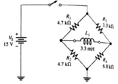
Chapter 11, Problem 22P
Determine the time constant for the circuit in Figure 11-47.
Expert Solution & Answer
Want to see the full answer?
Check out a sample textbook solution
Students have asked these similar questions
9. Sketch the VR waveform for the circuit in Figure 11–56, given the indicated relationship of the
input waveforms.
FIGURE 11-56
AO
G
VG-
VR
R
For a positive going pulse, the rising edge is.
O a. HIGH to LOW edge
O b. falling edge
O c. trailing edge
O d. leading edge
What is the voltage between nodes A and B in each circuit in Figure 12–73?
Chapter 11 Solutions
Electronics Fundamentals: Circuits, Devices & Applications
Ch. 11 - Lenz’s law states that the amount of voltage...Ch. 11 - An ideal inductor has no winding resistance.Ch. 11 - The total inductance of two parallel inductors is...Ch. 11 - The total inductance of parallel inductors is...Ch. 11 - The time constant of an RL circuit is given by the...Ch. 11 - Prob. 6TFQCh. 11 - Prob. 7TFQCh. 11 - Prob. 8TFQCh. 11 - Prob. 9TFQCh. 11 - Prob. 10TFQ
Ch. 11 - Prob. 1STCh. 11 - Prob. 2STCh. 11 - When the current through an inductor increases,...Ch. 11 - Prob. 4STCh. 11 - Prob. 5STCh. 11 - Prob. 6STCh. 11 - Prob. 7STCh. 11 - Prob. 8STCh. 11 - Prob. 9STCh. 11 - Prob. 10STCh. 11 - Prob. 11STCh. 11 - Prob. 1TSCCh. 11 - Prob. 2TSCCh. 11 - Symptom: The voltmeter 1 reading is 5 V, and the...Ch. 11 - Prob. 4TSCCh. 11 - Prob. 5TSCCh. 11 - Prob. 1PCh. 11 - Prob. 2PCh. 11 - Prob. 3PCh. 11 - A 12 V battery is connected across a coil with a...Ch. 11 - Prob. 5PCh. 11 - The current through a 100 mH coil is changing at a...Ch. 11 - Prob. 7PCh. 11 - Suppose that you require a total inductance of 50...Ch. 11 - Prob. 9PCh. 11 - Prob. 10PCh. 11 - Determine the total inductance of each circuit in...Ch. 11 - Determine the total inductance of each circuit in...Ch. 11 - Prob. 13PCh. 11 - In a series RL circuit, determine how long it...Ch. 11 - Prob. 15PCh. 11 - In Figure 11-45, calculate the current at each of...Ch. 11 - Prob. 17PCh. 11 - Find the total reactance for each circuit in...Ch. 11 - Determine the total rms current in Figure 11-46....Ch. 11 - What frequency will produce a total rms current of...Ch. 11 - Prob. 21PCh. 11 - Determine the time constant for the circuit in...Ch. 11 - Prob. 23PCh. 11 - Prob. 24PCh. 11 - What is the current in the inductor 1.0s after the...Ch. 11 - Prob. 26PCh. 11 - Prob. 27PCh. 11 - Prob. 28PCh. 11 - Prob. 29PCh. 11 - Prob. 30PCh. 11 - Prob. 32P
Knowledge Booster


Learn more about
Need a deep-dive on the concept behind this application? Look no further. Learn more about this topic, electrical-engineering and related others by exploring similar questions and additional content below.Similar questions
- Q6) The waveform of the voltage obtained after rectification is of a -----nature and therefore contains .harmonics a. Sinusoidal O b. Triangular c. Pulsating O d. Repetitive Oarrow_forwardVery urgent. Draw the waveforms of the voltage at the load (RL) end, the voltage at the R end, the voltage at the L end and the current 1 when the switch K is turned to position 2 after a long enough time.arrow_forwardConsider the following statements :A clamper circuit 1. adds or subtracts a dc voltage to a waveform 2. does not change the waveform 3. amplifies the waveform Which are correct? * O 1,2 O 1,3 O 1, 2, 3 O 2,3arrow_forward
- Calculate circuit values below. How does the total circuit impedence change as the frequency increases from 500 HZ to 50 Khz? How does the total current change as those frequencies increase?arrow_forwardSingle-pole and double-pole switch symbols are shown as a. single break. b. double break. c. NO and NC. d. all of the above.arrow_forward5. Name two methods used to make a DC multirange ammeter.arrow_forward
- The HP and LP switches are connected in __________ with the contactor coil. a. series b. parallelarrow_forwardWith a counter 10 lights will be controlled. At the first clock pulse all lights will be ON (1). at the following pulses, lights will be off from inside to outside and the ones that are OFF will not be ON. According to which modulo must this design work ? O 5 2 10arrow_forwardMillmans theory current thru 5ohmarrow_forward
- In the following figure find sa Asa turns ratio is A.O-7E A.07001arrow_forwardA technician connects a counter to the DAC of Figure 11-3 to perform a staircase test using a 1-kHzclock. The result is shown in Figure 11-36. What is the probable cause of the incorrect staircase signal?arrow_forwardRc does not look like a standard resistor value? and what about choosing value for Re, it has to be standard value as wellarrow_forward
arrow_back_ios
SEE MORE QUESTIONS
arrow_forward_ios
Recommended textbooks for you
 Electricity for Refrigeration, Heating, and Air C...Mechanical EngineeringISBN:9781337399128Author:Russell E. SmithPublisher:Cengage Learning
 Delmar's Standard Textbook Of ElectricityElectrical EngineeringISBN:9781337900348Author:Stephen L. HermanPublisher:Cengage Learning
 Power System Analysis and Design (MindTap Course ...Electrical EngineeringISBN:9781305632134Author:J. Duncan Glover, Thomas Overbye, Mulukutla S. SarmaPublisher:Cengage Learning
Electricity for Refrigeration, Heating, and Air C...
Mechanical Engineering
ISBN:9781337399128
Author:Russell E. Smith
Publisher:Cengage Learning
Delmar's Standard Textbook Of Electricity
Electrical Engineering
ISBN:9781337900348
Author:Stephen L. Herman
Publisher:Cengage Learning
Power System Analysis and Design (MindTap Course ...
Electrical Engineering
ISBN:9781305632134
Author:J. Duncan Glover, Thomas Overbye, Mulukutla S. Sarma
Publisher:Cengage Learning
Fault Analysis in Power Systems part 1a; Author: GeneralPAC: Power System Tutorials;https://www.youtube.com/watch?v=g8itg4MOjok;License: Standard youtube license