
Electronics Fundamentals: Circuits, Devices & Applications
8th Edition
ISBN: 9780135072950
Author: Thomas L. Floyd, David Buchla
Publisher: Prentice Hall
expand_more
expand_more
format_list_bulleted
Videos
Textbook Question
Chapter 11, Problem 18P
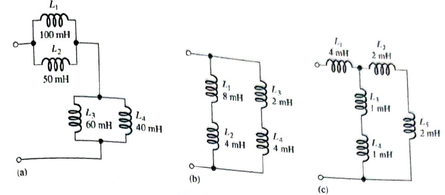
Find the total reactance for each circuit in Figure 11-43 when a 400 Hz voltage is applied.
Expert Solution & Answer
Want to see the full answer?
Check out a sample textbook solution
Students have asked these similar questions
number 42 a,b,c
what is the value of the total capacitive reactance in each circuit in figure 12-81
can you show the steps of these
book- principles of electric circuits 10th edition
Consider the following statements :A clamper circuit 1. adds or subtracts a
dc voltage to a waveform 2. does not change the waveform 3. amplifies
the waveform Which are correct? *
O 1,2
O 1,3
O 1, 2, 3
O 2,3
An A C voltmeter reads 250 V What is ts peak and nstantaneous values if the frequency of alternating voltage is 50H2?
Chapter 11 Solutions
Electronics Fundamentals: Circuits, Devices & Applications
Ch. 11 - Lenz’s law states that the amount of voltage...Ch. 11 - An ideal inductor has no winding resistance.Ch. 11 - The total inductance of two parallel inductors is...Ch. 11 - The total inductance of parallel inductors is...Ch. 11 - The time constant of an RL circuit is given by the...Ch. 11 - Prob. 6TFQCh. 11 - Prob. 7TFQCh. 11 - Prob. 8TFQCh. 11 - Prob. 9TFQCh. 11 - Prob. 10TFQ
Ch. 11 - Prob. 1STCh. 11 - Prob. 2STCh. 11 - When the current through an inductor increases,...Ch. 11 - Prob. 4STCh. 11 - Prob. 5STCh. 11 - Prob. 6STCh. 11 - Prob. 7STCh. 11 - Prob. 8STCh. 11 - Prob. 9STCh. 11 - Prob. 10STCh. 11 - Prob. 11STCh. 11 - Prob. 1TSCCh. 11 - Prob. 2TSCCh. 11 - Symptom: The voltmeter 1 reading is 5 V, and the...Ch. 11 - Prob. 4TSCCh. 11 - Prob. 5TSCCh. 11 - Prob. 1PCh. 11 - Prob. 2PCh. 11 - Prob. 3PCh. 11 - A 12 V battery is connected across a coil with a...Ch. 11 - Prob. 5PCh. 11 - The current through a 100 mH coil is changing at a...Ch. 11 - Prob. 7PCh. 11 - Suppose that you require a total inductance of 50...Ch. 11 - Prob. 9PCh. 11 - Prob. 10PCh. 11 - Determine the total inductance of each circuit in...Ch. 11 - Determine the total inductance of each circuit in...Ch. 11 - Prob. 13PCh. 11 - In a series RL circuit, determine how long it...Ch. 11 - Prob. 15PCh. 11 - In Figure 11-45, calculate the current at each of...Ch. 11 - Prob. 17PCh. 11 - Find the total reactance for each circuit in...Ch. 11 - Determine the total rms current in Figure 11-46....Ch. 11 - What frequency will produce a total rms current of...Ch. 11 - Prob. 21PCh. 11 - Determine the time constant for the circuit in...Ch. 11 - Prob. 23PCh. 11 - Prob. 24PCh. 11 - What is the current in the inductor 1.0s after the...Ch. 11 - Prob. 26PCh. 11 - Prob. 27PCh. 11 - Prob. 28PCh. 11 - Prob. 29PCh. 11 - Prob. 30PCh. 11 - Prob. 32P
Knowledge Booster


Learn more about
Need a deep-dive on the concept behind this application? Look no further. Learn more about this topic, electrical-engineering and related others by exploring similar questions and additional content below.Similar questions
- What is the minimum AC voltage rating of each capacitor in Question 11?arrow_forwardCan Ohm's Law be applied to a capacitor in an alternating current circuit?arrow_forward17. At what anode voltage (VA) will each PUT in Figure 11–60 begin to conduct? VB VB +20 V +9 V R2 47 kN R2 VAO VAO 12 kN R3 10 kΩ R3 47 kΩ 470 Ω 330 Ω (a) (b)arrow_forward
- QUESTION 3 An inductor and a 330 ohm resistor are connected in series with a function generator. The current is 89.8mA RMS 5kHz. The reactive power is 3.04 var. Find the value of the inductance. O 12mH O 24mH O 6mH O 18mHarrow_forward9. Sketch the VR waveform for the circuit in Figure 11–56, given the indicated relationship of the input waveforms. FIGURE 11-56 AO G VG- VR Rarrow_forwardThe inductive reactance (in ohms) of a 0.06 H coil connected to a 120-V, 60-Hz source is Blank 1. The resulting value must be rounded off to the nearest thousandths.arrow_forward
- The potential difference is measured in .volt True O False Oarrow_forwardWhen a direct voltage of 90V is applied to a coil, 15A direct current flows from the source. When 90V 50Hz alternating voltage is applied, 9A alternating current flows. What is the effective active power of this coil when 90V 50Hz alternating voltage is applied?arrow_forwardIf three inductors connected in series 0.06 H,0.05H,0.1H.What would be the inductive reactance of the circuit?Assume The inductors are connected to a 60Hz line?arrow_forward
- woq edt m bomer enbbA ng mereme spe LeeremAe Cm.tep A resistor and inductor are connected in parallel to a 400 Hz line. The inductor has a voltage drop of 136 volts across it. What is the voltage drop across the resistor?arrow_forwardFind the reactance voltage when current is changed from -2A to 2A in 4 sec and self inductance is 1H?arrow_forward24. A sinusoidal voltage is applied to the resistive circuit in Figure 11-80. Determine the following: Figure 11-80 10 V @ ar8 R 1.0 ΚΩ d. Ipp e. i at the positive peakarrow_forward
arrow_back_ios
SEE MORE QUESTIONS
arrow_forward_ios
Recommended textbooks for you
 Electricity for Refrigeration, Heating, and Air C...Mechanical EngineeringISBN:9781337399128Author:Russell E. SmithPublisher:Cengage Learning
 Delmar's Standard Textbook Of ElectricityElectrical EngineeringISBN:9781337900348Author:Stephen L. HermanPublisher:Cengage Learning
Electricity for Refrigeration, Heating, and Air C...
Mechanical Engineering
ISBN:9781337399128
Author:Russell E. Smith
Publisher:Cengage Learning
Delmar's Standard Textbook Of Electricity
Electrical Engineering
ISBN:9781337900348
Author:Stephen L. Herman
Publisher:Cengage Learning
02 - Sinusoidal AC Voltage Sources in Circuits, Part 1; Author: Math and Science;https://www.youtube.com/watch?v=8zMiIHVMfaw;License: Standard Youtube License