Introductory Circuit Analysis (13th Edition)
13th Edition
ISBN: 9780133923605
Author: Robert L. Boylestad
Publisher: PEARSON
expand_more
expand_more
format_list_bulleted
Question

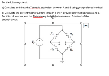
Transcribed Image Text:For the following circuit:
a) Calculate and draw the Thévenin equivalent between A and B using your preferred method.
b) Calculate the current that would flow through a short circuit occurring between A and B.
For this calculation, use the Thévenin equivale between A and B instead of the
original circuit.
VF
R3
R₁
RA
R2
C
Expert Solution
This question has been solved!
Explore an expertly crafted, step-by-step solution for a thorough understanding of key concepts.
Step by stepSolved in 2 steps with 4 images

Knowledge Booster
Similar questions
- Consider the circuit shown in the figure below. R₁ = R2= 11.00 and R3 =R4= 5.00 2 and Rs 20 Ω. a. Color code and reduce the circuit section to one equivalent resistor. Show each step and combine the resistors SYMBOLLICALLY before plugging in any numbers. W R4 a R1 W R2 W R3 W 25.0 V b. Find the potential difference between points a and b. b C. Find the current in the R5. W R5arrow_forwardPlease answer in typing format please ASAP for Please I will like it please ASAP please.....arrow_forwardHolds list UACO 50 V R1 = 10 ohms R2 = R3 = 25 ohms 15 ohms A. This is a circuit. ohms. (Round your answer to one decimal place.) B. The total resistance of this cirucit is amps. (Round your answer to one decimal place.) C. The total current flow in this circuit is amps.(Round your answer to the enarest whole number.) D. The current flow through R1 is volts. (Round your answer to the nearest whole number.) E. The voltage across R2 isarrow_forward
- Write the voltage node equations needed to find the six voltage nodes (a) to (f). Do not simplify. Make sure to make reference to the figure.arrow_forwardElectrical Engineering For the final problem, consider the following circuit diagram: 12 Q 30 V Vx 60 Q 2"Vx B 6) For this circuit, please find and draw: a. The Thevenin equivalent circuit between A and B, using external excitation to find R. b. The Norton cquivalent circuit berween A and B. c. Review section 3-8 from the text. What value load resistor connected between A and B would yield maximum power transfer? How much power woukd this be?arrow_forward#2 hello can you find , ir1, ir2 ir3 rt, it ,and pt . Thank you please show me how to do my homeworkarrow_forward
- For the given circuit below, provide the following unknowns: ti R2 V1 60V 1092 R1 www 1092 R3 www 1092 R4 1092 R5 1092 + Vo R7 1092 R6 1092 a. Number of nodes, branches, loops and mesh R8 1092arrow_forwardFor the circuit shown, the battery has a voltage of 13 V, the resistor has a resistance of 100 Ω, and the diode has a zener voltage of 6 V. Determine the maximum current iL that can be supplied to the load while the diode regulates the current. voltage. NEED A NEAT HAND WRITTEN SOLUTION WITH EXPLANATION ONLY OTHERWISE WILL LEAVE A DOWNVOTE..arrow_forwardLrocedure A- Kirchhoff's voltage law: The circuit in Figure 2 will be used o test the valdity of Kirchhoffs voltage law, Figure (2) Construct the circuit as shown in the figure (2). Measure the power supply output voltage and the potential drops across each of the thrae resistors. Record these measurements in your lab notebook as in the following table: University of Ti-Qar/ Departmnt of Elctricl aad Fectronlc Enginearing / Prepared by M 5¢ Al Karvem Soes 1+ Stage: Fundamentals of Flectrical Engineering | Lob 3 - Kirchhoff's Laws. 201520, Table 1; data collected for testing the validity of Kirchhot?s voltage law. 3)From your experimental data (table 2), calculate the total current into the node point P. Now calculate the total current out of the node point P along with its uncertainty. Does the current into the node agree with the current out of the node within experimental uncertainty?arrow_forward
arrow_back_ios
SEE MORE QUESTIONS
arrow_forward_ios
Recommended textbooks for you
 Introductory Circuit Analysis (13th Edition)Electrical EngineeringISBN:9780133923605Author:Robert L. BoylestadPublisher:PEARSON
 Delmar's Standard Textbook Of ElectricityElectrical EngineeringISBN:9781337900348Author:Stephen L. HermanPublisher:Cengage Learning
 Programmable Logic ControllersElectrical EngineeringISBN:9780073373843Author:Frank D. PetruzellaPublisher:McGraw-Hill Education
 Fundamentals of Electric CircuitsElectrical EngineeringISBN:9780078028229Author:Charles K Alexander, Matthew SadikuPublisher:McGraw-Hill Education
 Electric Circuits. (11th Edition)Electrical EngineeringISBN:9780134746968Author:James W. Nilsson, Susan RiedelPublisher:PEARSON
 Engineering ElectromagneticsElectrical EngineeringISBN:9780078028151Author:Hayt, William H. (william Hart), Jr, BUCK, John A.Publisher:Mcgraw-hill Education,

Introductory Circuit Analysis (13th Edition)
Electrical Engineering
ISBN:9780133923605
Author:Robert L. Boylestad
Publisher:PEARSON

Delmar's Standard Textbook Of Electricity
Electrical Engineering
ISBN:9781337900348
Author:Stephen L. Herman
Publisher:Cengage Learning

Programmable Logic Controllers
Electrical Engineering
ISBN:9780073373843
Author:Frank D. Petruzella
Publisher:McGraw-Hill Education

Fundamentals of Electric Circuits
Electrical Engineering
ISBN:9780078028229
Author:Charles K Alexander, Matthew Sadiku
Publisher:McGraw-Hill Education

Electric Circuits. (11th Edition)
Electrical Engineering
ISBN:9780134746968
Author:James W. Nilsson, Susan Riedel
Publisher:PEARSON

Engineering Electromagnetics
Electrical Engineering
ISBN:9780078028151
Author:Hayt, William H. (william Hart), Jr, BUCK, John A.
Publisher:Mcgraw-hill Education,