Introductory Circuit Analysis (13th Edition)
13th Edition
ISBN: 9780133923605
Author: Robert L. Boylestad
Publisher: PEARSON
expand_more
expand_more
format_list_bulleted
Question
thumb_up100%

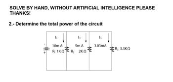
Transcribed Image Text:SOLVE BY HAND, WITHOUT ARTIFICIAL INTELLIGENCE PLEASE
THANKS!
2.- Determine the total power of the circuit
I₁
12
13
10m A
5m A
3.03mA
R3 3.3KQ
+
R₁ 1KQ
R₂ 2KQ
Expert Solution
This question has been solved!
Explore an expertly crafted, step-by-step solution for a thorough understanding of key concepts.
Step by stepSolved in 2 steps with 2 images

Knowledge Booster
Similar questions
- can you do 5 please elec eng maths helparrow_forwardThis is a practice problem from the Introduction to Electronics course in my Electrical Engineering program. Could you please walk me through the steps of solving it so that I can solve more complicated ones in the future? Thank you for your assistance.arrow_forwardPlease answer both questions. The answers are given but I'd like to see all the steps Please answer both i will upvotearrow_forward
- This is a practice question from my Introduction to Circuits course. What is the process for solving this? Thank you for your assistance.arrow_forward1.Utilize an appropriate R-C circuit powered by a 120 V DC source. This RC circuit will be the energy source to power a single Neon Lamp. 2. Neon and other gas-based lamps often require a threshold voltage before they turn "on", i.e. emit light. The neon lamp you will use has a turn-on voltage of 70 V. In the provided LTspice model of such a neon lamp, you can explore how this light turns on and off (i.e. the current through the lamp is high when the lamp is on), when it is powered by a pulsed voltage source. Play around with the pulsed source parameters to investigate the lamp's behavior. However, keep the lamps LIspice parameters fixed (i.e. do not change the attributes of the lamp). 3. Using the RC circuit Power your Neon Lamp so that it turns on every 0.1 seconds (10 Hz frequency). The time for which it remains on is not critical, but should obviously be much less than 0.1 seconds.arrow_forwardIn the figure you have a RL circuit with direct current. All resistors have resistance 30.0 , the inductors is 3.0 H. The battery provides a voltage of 840.0 V. At t=0 close the switch. At that instant, what are a) the current in the resistor R1? b) the current in the resistor R3? c) the voltage at the inductor L? +1 V m R1 switch M R2 A A V www R3arrow_forward
- A voltage of .... appears between the terminals of a combination of a 100 mF capacitor and a 12 oms resistor in parallel. Calculate the power absorbed by the parallel combination. Note: I leave the image of the exercises in Spanish, but it is easy to understand. Also in the other image is the correct final answer, for checking. IMPORTANT:Please, preferably the procedure should be digital, not on paper.This way I understand better.I would appreciate it very much!arrow_forwardBasic Electrical Engineering: Inductance and Capacitance You are an electrician working in an industrial plant. You discover the problem with a certain machine is a defective capacitor. The capacitor is connected to a 240-V AC circuit. The information on the capacitor reveals that it has a capacitance value of 10 µF and a voltage rating of 240 V AC. The only 10-µF capacitor in the storeroom is marked with a voltage rating 350 VDC. Can this capacitor be used to replace the defective capacitor? Explain your answer.arrow_forwardElectric Circuits / Mutual Induction Topic: I need the solution to the questionarrow_forward
arrow_back_ios
SEE MORE QUESTIONS
arrow_forward_ios
Recommended textbooks for you
 Introductory Circuit Analysis (13th Edition)Electrical EngineeringISBN:9780133923605Author:Robert L. BoylestadPublisher:PEARSON
 Delmar's Standard Textbook Of ElectricityElectrical EngineeringISBN:9781337900348Author:Stephen L. HermanPublisher:Cengage Learning
 Programmable Logic ControllersElectrical EngineeringISBN:9780073373843Author:Frank D. PetruzellaPublisher:McGraw-Hill Education
 Fundamentals of Electric CircuitsElectrical EngineeringISBN:9780078028229Author:Charles K Alexander, Matthew SadikuPublisher:McGraw-Hill Education
 Electric Circuits. (11th Edition)Electrical EngineeringISBN:9780134746968Author:James W. Nilsson, Susan RiedelPublisher:PEARSON
 Engineering ElectromagneticsElectrical EngineeringISBN:9780078028151Author:Hayt, William H. (william Hart), Jr, BUCK, John A.Publisher:Mcgraw-hill Education,

Introductory Circuit Analysis (13th Edition)
Electrical Engineering
ISBN:9780133923605
Author:Robert L. Boylestad
Publisher:PEARSON

Delmar's Standard Textbook Of Electricity
Electrical Engineering
ISBN:9781337900348
Author:Stephen L. Herman
Publisher:Cengage Learning

Programmable Logic Controllers
Electrical Engineering
ISBN:9780073373843
Author:Frank D. Petruzella
Publisher:McGraw-Hill Education

Fundamentals of Electric Circuits
Electrical Engineering
ISBN:9780078028229
Author:Charles K Alexander, Matthew Sadiku
Publisher:McGraw-Hill Education

Electric Circuits. (11th Edition)
Electrical Engineering
ISBN:9780134746968
Author:James W. Nilsson, Susan Riedel
Publisher:PEARSON

Engineering Electromagnetics
Electrical Engineering
ISBN:9780078028151
Author:Hayt, William H. (william Hart), Jr, BUCK, John A.
Publisher:Mcgraw-hill Education,