Introductory Circuit Analysis (13th Edition)
13th Edition
ISBN: 9780133923605
Author: Robert L. Boylestad
Publisher: PEARSON
expand_more
expand_more
format_list_bulleted
Question
I need a handwritten solution from the expert, along with proof of the answer.

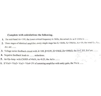
Transcribed Image Text:Complete with calculations the following.
1. The mid-band Av=100, the lower critical frequency is 1kHz, the actual Av at f-10Hz is.....
2. Three stages of identical amplifier, every single stage has f₁=1kHz, f-20kHz, Av-10, the total fur, fHT.
AVT are......
3. Voltage series feedback circuit with A=100, B=0.09, Zi=10k2, Zo=100k, the Avf, Zif, Zof are
4. Negative feedback leads to ... reductions.
5. An Op-Amp. with CMRR of 40dB, Ac=0.25, the Ad is......
D.
+8 Av
6. If Vin1= Vin2= Vin3= Vin4-3V of summing amplifier with unity gain, the Vo is
Expert Solution
This question has been solved!
Explore an expertly crafted, step-by-step solution for a thorough understanding of key concepts.
Step by stepSolved in 2 steps with 6 images

Knowledge Booster
Similar questions
- The circuit of Figure below uses current- (or shunt-) feedback bias. The Si transistor has ICEO = 0, B = 100, Rc= 2k2, Vcc = 12 V. Assume that; (VCEQ = Vcc /2). A. Find the value of Ibq B. Find the value of Rf C. Find the value of Rearrow_forwardA. Find the value of Ibq B. Find the value of Rf C. Find the value of (Re) tarrow_forwardComplete with calculations the following 1. The mid-band Av=100, the lower critical frequency is 1kHz, the actual Av at f-10Hz is..... 2. Three stages of identical amplifier, every single stage has fi-1kHz, fi-20kHz, Av 10, the total fur. fir. AVT are...... 3. Voltage series feedback circuit with A-100, B-0.09, Zi-10ks2, Zo-100k2, the Avf, Zif, Zof are. 4. Negative feedback leads to ...... reductions. 5. An Op-Amp. with CMRR of 40dB, Ac 0.25, the Ad is...... D. 6. If Vin1= Vin2= Vin3 Vin4-3V of summing amplifier with unity gain, the Vo is.....arrow_forward
- The term duty cycle refers to the amount of time a signal is complete cycle. A. off compared to the period of one B. on The output voltage of op-amp is positive saturation, when the voltage applied to the input is greater than the input. A. inverting B. noninverting A square wave that is 20V at its high state and OV when it is off will produce an average DC when its duty cycle is 75%. Formula: VOUT = Duty Cycle * Peak voltage voltage of A. 7.5V B. 10V C. 15Varrow_forwardThe amplifier configuration shown in figure below is a a) common emitter b) common collector c) common base d) base follower configuration, where the is at ac ground, and the ac output voltage a) collector B) emitter C) capacitor D) base with the input. A) amplified and 180deg out of phase B) almost equal and 180degree out of phase C) almost equal and in phase D) amplified and in phasearrow_forwardDraw a n-p-n transistor connected in circuit common base (CB).Draw the input current-voltage characteristic, the output current-voltage characteristicsand the graph giving dependence of the output current as function of the input current.Define the amplification gain of this circuit.arrow_forward
- I need the answer as soon as possiblearrow_forwardQ1 Design an operational-amplifier circuit using two inverting configurations to produce the output vo = +201 + 0.5v2 – 0.2v3 – 1v4. Choose feedback resistor Rf = 220kN for each amplifier. %3D | -arrow_forwardFigure 6 shows a circuit where feedback is provided between the drain and gate of the transistor M1 Q6 Draw the small signal equivalent circuit of the open loop circuit obtained by breaking the loop at the gate of transistor M1 (suitable for the analysis in the mid band frequency range). Consider Cg as short circuit in the model and state any assumption. (a) (b) State the necessary conditions for the oscillation to occur in the circuit. Using the conditions from (b), derive an expression for the amplifier oscillation frequency fo. (c) Derive the necessary condition for the oscillation to occur in the circuit and state if you can conclude that the circuit will oscillate when considering the values of the inductances L2 = 8 LI = 2 mH; capacitors C = 2 nF; transconductance of the transistor gml = 1.4 mS; and resistors R1 = R2 = Rs : 10 k2. (d) %3D L2 L, R, Cg. C Vout Cp M1 R2 CG Rs Cs Vss = 0 V Figure 6arrow_forward
arrow_back_ios
SEE MORE QUESTIONS
arrow_forward_ios
Recommended textbooks for you
 Introductory Circuit Analysis (13th Edition)Electrical EngineeringISBN:9780133923605Author:Robert L. BoylestadPublisher:PEARSON
 Delmar's Standard Textbook Of ElectricityElectrical EngineeringISBN:9781337900348Author:Stephen L. HermanPublisher:Cengage Learning
 Programmable Logic ControllersElectrical EngineeringISBN:9780073373843Author:Frank D. PetruzellaPublisher:McGraw-Hill Education
 Fundamentals of Electric CircuitsElectrical EngineeringISBN:9780078028229Author:Charles K Alexander, Matthew SadikuPublisher:McGraw-Hill Education
 Electric Circuits. (11th Edition)Electrical EngineeringISBN:9780134746968Author:James W. Nilsson, Susan RiedelPublisher:PEARSON
 Engineering ElectromagneticsElectrical EngineeringISBN:9780078028151Author:Hayt, William H. (william Hart), Jr, BUCK, John A.Publisher:Mcgraw-hill Education,

Introductory Circuit Analysis (13th Edition)
Electrical Engineering
ISBN:9780133923605
Author:Robert L. Boylestad
Publisher:PEARSON

Delmar's Standard Textbook Of Electricity
Electrical Engineering
ISBN:9781337900348
Author:Stephen L. Herman
Publisher:Cengage Learning

Programmable Logic Controllers
Electrical Engineering
ISBN:9780073373843
Author:Frank D. Petruzella
Publisher:McGraw-Hill Education

Fundamentals of Electric Circuits
Electrical Engineering
ISBN:9780078028229
Author:Charles K Alexander, Matthew Sadiku
Publisher:McGraw-Hill Education

Electric Circuits. (11th Edition)
Electrical Engineering
ISBN:9780134746968
Author:James W. Nilsson, Susan Riedel
Publisher:PEARSON

Engineering Electromagnetics
Electrical Engineering
ISBN:9780078028151
Author:Hayt, William H. (william Hart), Jr, BUCK, John A.
Publisher:Mcgraw-hill Education,