
Delmar's Standard Textbook Of Electricity
7th Edition
ISBN: 9781337900348
Author: Stephen L. Herman
Publisher: Cengage Learning
expand_more
expand_more
format_list_bulleted
Related questions
Question
i need help
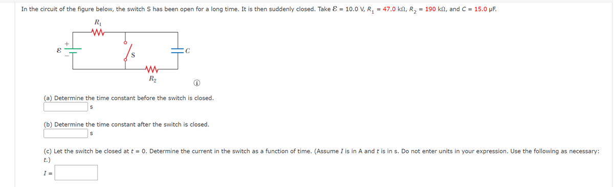

Transcribed Image Text:In the circuit of the figure below, the switch S has been open for a long time. It is then suddenly closed. Take Ɛ = 10.0 V, R₁ = 47.0 kN, R₂ = 190 kn, and C = 15.0 μF.
R₁
www
8
S
www
R₂
C
i
(a) Determine the time constant before the switch is closed.
S
(b) Determine the time constant after the switch is closed.
S
(c) Let the switch be closed at t=0. Determine the current in the switch as a function of time. (Assume I is in A and t is in s. Do not enter units in your expression. Use the following as necessary:
t.)
I =
Expert Solution
This question has been solved!
Explore an expertly crafted, step-by-step solution for a thorough understanding of key concepts.

Step by stepSolved in 2 steps

Knowledge Booster

Similar questions
- 1. A purely resistive circuit the current is leading by 90° with respect to voltage. 2. A purely inductive circuit the current is lag behind the voltage by 90°. 3. A purely capacitive circuit the current is lead by 90° with respect to the voltage. 4. A capacitor element stored magnetic energy. 5. An inductor element stored electrical energy. 6. Resistor elements consume power. 7. Angle between current and voltage is called power. 8. The power factor angle for a purely resistive is zero. 9. The power factor angle for a purely inductive load is -90°. 10. The power factor of a purely capacitive is leading.arrow_forwardIf the charging resistor was twice as large as the discharging resistor in Figure 4, theamplitudes of the charging and discharging waveforms would be ________.a. The sameb. Differentarrow_forwardThe circuit is in continuity mode before the switch is opened. What is the initial voltage of the capacitor Uco before opening the switch. I Select one: O a. Uco = 0 O b. Uco = RI O c. Uco=E O d. Uco= E R karrow_forward
- For the circuit shown in the figure, ϵ0=100Volt, R1=50Ω, R2=100Ω, C=2μF. What is the status of the capacitor immediately after the switch is closed, charged or discharged, and what is the initial current of the battery immediately after the switch is closed?arrow_forwardCalculate the voltage at 1.5¹ (milliseconds) for the following RC Circuit. Assume switch is closed and capacitor is in a charge state. t=0 LE -10 V oto R1 1kQ C1 1uFarrow_forwardIf the resistors used for charging and discharging were the same, the charging anddischarging waveform would be ________.a. Symmetricalb. Nonsymmetricalarrow_forward
- HELP plZ IN 10 MINUITSarrow_forwardBecause alternating current starts at zero, reaches a peak, and then returns to zero, there is always a variation in voltage and an effective value has to be determined. Select one: TRUE FALSEarrow_forwardThe figure displays two circuits with a charged capacitor that is to be discharged through a resistor when a switch is closed. In figure (a) below, R₁ = 23.32 and C₁ = 5.04 μF. In figure (b) below, R2 = 10.82 and C₂ = 8.10 μF. The ratio of the initial charges on the two capacitors is 902/901 = 1.61. At time t = 0, both switches are closed. At what time t do the two capacitors have the same charge? 0.0 (a) (b) Number i Unitsarrow_forward
- The circuit in the figure below contains two resistors, R1 = 4.00kΩ and R2 = 5.00kΩ, and two capacitors, C1 = 4.00uF and C2 = 5.00uF, connected to a battery with emf E = 120V. If no charges exist on the capacitors before switch S is closed, determine the charge q1 on capacitor C1 1.00ms after the switch is closed. Determine the charge q2 on capacitor C2 1.00ms after the switch is closed.arrow_forwardWhat will be initial current while charging a capacitor? o Infinity O Zero High O Lowarrow_forwardThe initial rate of current rise in an RL circuit is 300 amp per sec when 120 volts is suddenly impressed. What is the inductance of the circuit?arrow_forward
arrow_back_ios
SEE MORE QUESTIONS
arrow_forward_ios
Recommended textbooks for you
- Delmar's Standard Textbook Of ElectricityElectrical EngineeringISBN:9781337900348Author:Stephen L. HermanPublisher:Cengage Learning

 Power System Analysis and Design (MindTap Course ...Electrical EngineeringISBN:9781305632134Author:J. Duncan Glover, Thomas Overbye, Mulukutla S. SarmaPublisher:Cengage Learning
Delmar's Standard Textbook Of Electricity
Electrical Engineering
ISBN:9781337900348
Author:Stephen L. Herman
Publisher:Cengage Learning
Power System Analysis and Design (MindTap Course ...
Electrical Engineering
ISBN:9781305632134
Author:J. Duncan Glover, Thomas Overbye, Mulukutla S. Sarma
Publisher:Cengage Learning