The minimum work that must be supplied to the compressor and turbine due to irreversibilities.
Answer to Problem 143P
The minimum work that must be supplied to the compressor due to irreversibilities is 40.1kJ/kg.
The minimum work that is developed by the turbine due to irreversibilities is 34.8kJ/kg.
It can be noted that the compressor is more sensitive to irreversibilities than the turbine.
Explanation of Solution
Show the simple Brayton cycle, with air as the working fluid on T−s diagram.
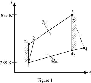
For the given Brayton cycle with air as the working fluid Ti, hi, and Pi are the temperature at ith state, specific enthalpy at ith state and pressure at ith state respectively.
Write the expression of temperature and pressure relation ratio for the compression process 1-2.
T2s=T1(P2P1)(k−1)/k (I)
Here, specific heat ratio is k.
Write the expression of efficiency of the compressor (ηC).
ηC=h2s−h1h2−h1
ηC=cp(T2s−T1)cp(T2−T1) (II)
Here, specific heat at constant pressure is cp.
Write the expression of temperature and pressure relation ratio for the expansion process 3-4.
T4s=T3(P4P3)(k−1)/k (III)
Write the expression of efficiency of the turbine (ηT).
ηT=h3−h4h3−h4s
ηT=cp(T3−T4)cp(T3−T4s) (IV)
For compression processes
Write the expression for the entropy change for the isentropic process 1-2s (s2s−s1).
s2s−s1=cplnT2sT1−RlnP2P1 (V)
Here, gas constant of air is R.
Write the expression for reversible work for the isentropic process 1-2s (wrev,1-2s).
wrev,1-2s=cp(T2s−T1)−T0(s2s−s1) (VI)
Here, temperature of the surroundings is T0.
Write the expression for the entropy change for the process 1-2 (s2−s1).
s2−s1=cplnT2T1−RlnP2P1 (VII)
Write the expression for the reversible work for the process 1-2 (wrev,1-2).
wrev,1-2=cp(T2−T1)−T0(s2−s1) (VIII)
Write the expression for the minimum work that must be supplied to the compressor due to irreversibilities (Δwrev,C).
Δwrev,C=wrev,1-2−wrev,1-2s (IX)
For expansion processes
Write the expression for the entropy change for the isentropic process 3-4s (s3−s4s).
s3−s4s=cplnT3T4s−RlnP3P4 (X)
Write the expression for the reversible work for the isentropic process 3-4s (wrev,3-4s).
wrev,3-4s=cp(T3−T4s)−T0(s3−s4s) (XI)
Write the expression for the entropy change for the process 3-4 (s3−s4).
s3−s4=cplnT3T4−RlnP3P4 (XII)
Write the expression for the reversible work for the process 3-4 (wrev,3-4).
wrev,3-4=cp(T3−T4)−T0(s3−s4) (XIII)
Write the expression for the minimum work that is developed by the turbine due to irreversibilities (Δwrev,T).
Δwrev,T=wrev,3-4s−wrev,3-4 (XIV)
Conclusion:
Substitute 288 K for T1, 12 for P2P1, and 1.4 for k in Equation (I).
T2s=(288 K)(12)1.4−1/1.4=585.8 K
Rearrange Equation (II), and solve for T2. Substitute 288 K for T1, 585.8 K for T2s, and 0.80 for ηC in Equation (II).
T2=T1+T2s−T1ηC=288 K+(585.8−288)K0.80=660.2 K
Substitute 873 K for T3, 112 for P4P3, and 1.4 for k in Equation (III).
T4s=(873 K)(112)1.4−1/1.4=429.2 K
Rearrange Equation (IV), and substitute 873 K for T3, 429.2 K for T4s, and 0.80 for ηT.
T4=T3−ηT(T3−T4s)=873 K−(0.80)(873 K−429.2 K)=518 K
Substitute 1.005 kJ/kg⋅K for cp, 585.8 K for T2s, 288 K for T1, 0.287 kJ/kg⋅K for R, and 12 for P2P1 in Equation (V).
s2s−s1=(1.005 kJ/kg⋅K)ln585.8 K288 K−(0.287 kJ/kg⋅K)ln(12)=0.0003998 kJ/kg⋅K
Substitute 1.005 kJ/kg⋅K for cp, 585.8 K for T2s, 288 K for T1, 288 K for T0, and 0.0003998 kJ/kg⋅K for (s2s−s1) in Equation (VI).
wrev,1-2s=(1.005 kJ/kg⋅K)(585.8−288) K−(288 K)(0.0003998 kJ/kg⋅K)=299.2 kJ/kg
Substitute 1.005 kJ/kg⋅K for cp, 660.2 K for T2, 288 K for T1, 0.287 kJ/kg⋅K for R, and 12 for P2P1 in Equation (VII).
s2−s1=(1.005 kJ/kg⋅K)ln660.2 K288 K−(0.287 kJ/kg⋅K)ln(12)=0.1206 kJ/kg⋅K
Substitute 1.005 kJ/kg⋅K for cp, 660.2 K for T2, 288 K for T1, 288 K for T0, and 0.1206 kJ/kg⋅K for (s2−s1) in Equation (VIII).
wrev,1-2=(1.005 kJ/kg⋅K)(660.2−288) K−(288 K)(0.1206 kJ/kg⋅K)=339.3 kJ/kg
Substitute 339.3 kJ/kg for wrev,1-2, and 299.2 kJ/kg for wrev,1-2s in Equation (IX).
Δwrev,C=(339.3−299.2) kJ/kg=40.1kJ/kg
Thus, the minimum work that must be supplied to the compressor due to irreversibilities is 40.1kJ/kg.
Substitute 1.005 kJ/kg⋅K for cp, 873 K for T3, 429.2 K for T4s, 0.287 kJ/kg⋅K for R, and 12 for P3P4 in Equation (X).
s3−s4s=(1.005 kJ/kg⋅K)ln873 K429.2 K−(0.287 kJ/kg⋅K)ln(12)=0.0003944 kJ/kg⋅K
Substitute 1.005 kJ/kg⋅K for cp, 873 K for T3, 429.2 K for T4s, 288 K for T0, and 0.0003944 kJ/kg⋅K for (s3−s4s) in Equation (XI).
wrev,3-4s=(1.005 kJ/kg⋅K)(873−429.2) K−(288 K)(0.0003944 kJ/kg⋅K)=445.9 kJ/kg
Substitute 1.005 kJ/kg⋅K for cp, 873 K for T3, 518.0 K for T4, 0.287 kJ/kg⋅K for R, and 12 for P3P4 in Equation (XII).
s3−s4=(1.005 kJ/kg⋅K)ln873 K518.0 K−(0.287 kJ/kg⋅K)ln(12)=−0.1885 kJ/kg⋅K
Substitute 1.005 kJ/kg⋅K for cp, 873 K for T3, 518.0 K for T4, 288 K for T0, and −0.1885 kJ/kg⋅K for (s3−s4) in Equation (XIII).
wrev,3-4=(1.005 kJ/kg⋅K)(873−518.0) K−(288 K)(−0.1885 kJ/kg⋅K)=411.1 kJ/kg
Substitute 445.9 kJ/kg for wrev,3-4s, and 411.1 kJ/kg for wrev,3-4 in Equation (XIV).
Δwrev,T=(445.9−411.1) kJ/kg=34.8kJ/kg
Thus, the minimum work that is developed by the turbine due to irreversibilities is 34.8kJ/kg.
It can be noted that the compressor is more sensitive to irreversibilities than the turbine.
Want to see more full solutions like this?
Chapter 9 Solutions
Thermodynamics: An Engineering Approach

- Please do not rely too much on AI, because its answer may be wrong. Please consider it carefully and give your own answer!!!!! You can borrow ideas from AI, but please do not believe its answer.Very very grateful! ( If you write by hand or don't use AI, I'll give you a big thumbs up ) Please do not copy other's work,i will be very very grateful!!Please do not copy other's work,i will be very very grateful!!arrow_forwardA thin uniform rod of mass m and length 2r rests in a smooth hemispherical bowl of radius r. A moment M = mgr horizontal plane. is applied to the rod. Assume that the bowl is fixed and its rim is in the HINT: It will help you to find the length l of that portion of the rod that remains outside the bowl. M 2r Ꮎ a) How many degrees of freedom does this system have? b) Write an equation for the virtual work in terms of the angle 0 and the motion of the center of mass (TF) c) Derive an equation for the variation in the position of the center of mass (i.e., Sŕƒ) a. HINT: Use the center of the bowl as the coordinate system origin for the problem. d) In the case of no applied moment (i.e., M = 0), derive an equation that can be used to solve for the equilibrium angle of the rod. DO NOT solve the equation e) In the case of an applied moment (i.e., M: = mgr 4 -) derive an equation that can be used to solve for the equilibrium angle of the rod. DO NOT solve the equation. f) Can the angle 0 and…arrow_forwardSolve this problem and show all of the workarrow_forward
- Solve this problem and show all of the workarrow_forwardSolve this problem and show all of the workarrow_forwardPlease do not rely too much on chatgpt, because its answer may be wrong. Please consider it carefully and give your own answer. You can borrow ideas from gpt, but please do not believe its answer.Very very grateful! Please do not copy other's work,i will be very very grateful!!Please do not copy other's work,i will be very very grateful!!arrow_forward
- = The frame shown is fitted with three 50 cm diameter frictionless pulleys. A force of F = 630 N is applied to the rope at an angle ◊ 43°. Member ABCD is attached to the wall by a fixed support at A. Find the forces indicated below. Note: The rope is tangent to the pully (D) and not secured at the 3 o'clock position. a b •C *су G E e d BY NC SA 2013 Michael Swanbom Values for dimensions on the figure are given in the following table. Note the figure may not be to scale. Variable Value a 81 cm b 50 cm с 59 cm d 155 cm For all answers, take x as positive to the right and positive upward. At point A, the fixed support exerts a force of: A = + ĴN and a reaction couple of: →> ΜΑ Member CG is in Select an answer magnitude У as k N-m. and carries a force of N.arrow_forwardThe lower jaw AB [Purple 1] and the upper jaw-handle AD [Yellow 2] exert vertical clamping forces on the object at R. The hand squeezes the upper jaw-handle AD [2] and the lower handle BC [Orane 4] with forces F. (Member CD [Red 3] acts as if it is pinned at D, but, in a real vise-grips, its position is actually adjustable.) The clamping force, R, depends on the geometry and on the squeezing force F applied to the handles. Determine the proportionality between the clamping force, R, and the squeezing force F for the dimensions given. d3 d4 R 1 B d1 2 d2 D... d5 F 4 F Values for dimensions on the figure are given in the following table. Note the figure may not be to scale. Variable Value d1 65 mm d2 156 mm d3 50 mm 45 d4 d5 113 mm 30 mm R = Farrow_forwardA triangular distributed load of max intensity w =460 N/m acts on beam AB. The beam is supported by a pin at A and member CD, which is connected by pins at C and D respectively. Determine the reaction forces at A and C. Enter your answers in Cartesian components. Assume the masses of both beam AB and member CD are negligible. cc 040 BY NC SA 2016 Eric Davishahl W A C D -a- B Ул -b- x Values for dimensions on the figure are given in the following table. Note the figure may not be to scale. Variable Value α 5.4 m b 8.64 m C 3.24 m The reaction at A is A = i+ ĴN. λ = i+ Ĵ N. The reaction at C is C =arrow_forward
- 56 Clamps like the one shown are commonly used in woodworking applications. This clamp has the dimensions given in the table below the figure, and its jaws are mm thick (in the direction perpendicular to the plane of the picture). a.) The screws of the clamp are adjusted so that there is a uniform pressure of P = 150 kPa being applied to the workpieces by the jaws. Determine the force carried in each screw. Hint: the uniform pressure can be modeled in 2-D as a uniform distributed load with intensity w = Pt (units of N/m) acting over the length of contact between the jaw and the workpiece. b.) Determine the minimum vertical force (parallel to the jaws) required to pull either one of the workpieces out of the clamp jaws. Use a coefficient of static friction between all contacting surfaces of μs = 0.56 and the same clamping pressure given for part (a). 2013 Michael Swanbom A B C a Values for dimensions on the figure are given in the following table. Note the figure may not be to scale.…arrow_forwardDetermine the force in each member of the space truss given F=5 kN. Use positive to indicate tension and negative to indicate compression. F E Z -2 m. B 3 m C 5 m 3 m A -4 m. AB = KN FAC = FAD = KN KN KN FBC = KN FBD FBE = = KN Farrow_forwardA short brass cyclinder (denisty=8530 kg/m^3, cp=0.389 kJ/kgK, k=110 W/mK, and alpha=3.39*10^-5 m^2/s) of diameter 4 cm and height 20 cm is initially at uniform temperature of 150 degrees C. The cylinder is now placed in atmospheric air at 20 degrees C, where heat transfer takes place by convection with a heat transfer coefficent of 40 W/m^2K. Calculate (a) the center temp of the cylinder, (b) the center temp of the top surface of the cylinder, and (c) the total heat transfer from the cylinder 15 min after the start of the cooling. Solve this problem using the analytical one term approximation method. (Answer: (a) 45.7C, (b)45.3C, (c)87.2 kJ)arrow_forward
 Elements Of ElectromagneticsMechanical EngineeringISBN:9780190698614Author:Sadiku, Matthew N. O.Publisher:Oxford University Press
 Mechanics of Materials (10th Edition)Mechanical EngineeringISBN:9780134319650Author:Russell C. HibbelerPublisher:PEARSON
 Thermodynamics: An Engineering ApproachMechanical EngineeringISBN:9781259822674Author:Yunus A. Cengel Dr., Michael A. BolesPublisher:McGraw-Hill Education
 Control Systems EngineeringMechanical EngineeringISBN:9781118170519Author:Norman S. NisePublisher:WILEY
 Mechanics of Materials (MindTap Course List)Mechanical EngineeringISBN:9781337093347Author:Barry J. Goodno, James M. GerePublisher:Cengage Learning
 Engineering Mechanics: StaticsMechanical EngineeringISBN:9781118807330Author:James L. Meriam, L. G. Kraige, J. N. BoltonPublisher:WILEY